Nissan Juke F15. Manual - part 996


  Index      Nissan     Nissan Juke F15 (2015 year) - Service and Repair Manual


Search            


Content   ..  994  995  996  997   ..


Nissan Juke F15. Manual - part 996


MWI-6

< SYSTEM DESCRIPTION >

COMPONENT PARTS

SYSTEM DESCRIPTION

COMPONENT PARTS

METER SYSTEM
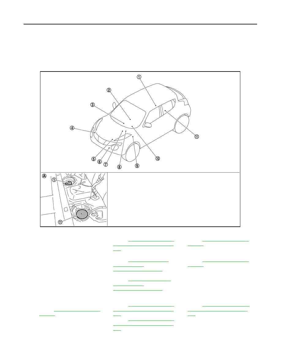
METER SYSTEM : Component Parts Location

INFOID:0000000012201293

1.

Fuel level sensor unit (main)

2.

CVT shift selector
Refer to 

TM-156, "CVT CONTROL 

SYSTEM : Component Parts Loca-
tion"

3.

A/C auto amp.
Refer to 

HAC-7, "Component Parts 

Location"

4.

Washer level switch

5.

ECM
Refer to 

EC-27, "ENGINE CON-

TROL SYSTEM : 
Component Parts Location"

 (MR for 

NISMO RS models)
Refer to 

EC-600, "ENGINE CON-

TROL SYSTEM : 
Component Parts Location"

 (MR 

except for NISMO RS models)

6.

Ambient sensor
Refer to 

HAC-7, "Component Parts 

Location"

7.

ABS actuator and electric unit (con-
trol unit)
Refer to 

BRC-9, "Component Parts 

Location"

8.

TCM
Refer to 

TM-156, "CVT CONTROL 

SYSTEM : Component Parts Loca-
tion"

 (RE0F10B)

Refer to 

TM-361, "CVT CONTROL 

SYSTEM : Component Parts Loca-
tion"

 (RE0F10D)

9.

BCM
Refer to 

BCS-5, "BODY CONTROL 

SYSTEM : Component Parts Loca-
tion"

10. Combination meter

11. Fuel level sensor unit (sub)

A.

Rear seat (bottom)

JSNIA3527ZZ

MWI

COMPONENT PARTS

MWI-7

< SYSTEM DESCRIPTION >

C

D

E

F

G

H

I

J

K

L

M

B

A

O

P

METER SYSTEM : Component Description

INFOID:0000000012201294

Unit

Description

Combination meter

• Provides the driver with various kinds of vehicle information via the CAN communication line and 

the use of signals through the hard wire.

• Includes the signal buffer to transmit received signals to other units.
• For functions of the combination meter, refer to 

MWI-8, "METER SYSTEM : System Description"

.

ECM

Transmits the following signals to the combination meter via CAN communication.
• Engine coolant temperature signal
• Engine status signal
• Fuel consumption monitor signal
• Fuel filler cap warning display signal
• Oil pressure warning lamp signal
• Engine speed signal (M/T models)

ABS actuator and electric unit 
(control unit)

Transmits the vehicle speed signal to the combination meter via CAN communication.

BCM

Transmits the following signals to the combination meter via CAN communication.
• Door switch signal
• Position light request signal
• Low tire pressure warning lamp signal

TCM

Transmits the following signals to the combination meter.
• Shift position signal
• Manual mode shift refusal signal
• Manual mode signal
• Non-manual mode signal
• Manual mode shift up signal
• Manual mode shift down signal
• Engine speed signal (CVT models)

CVT shift selector

Transmits the following signals to the combination meter.
• Manual mode signal
• Non-manual mode signal
• Manual mode shift up signal
• Manual mode shift down signal

Paddle shifter

Transmits paddle shifter up signal paddle shifter down signal to the combination meter.

Fuel level sensor unit

Transmits the fuel level sensor signal to the combination meter.

Ambient sensor

Transmits the ambient sensor signal to the A/C auto amp. and the combination meter.

A/C auto amp.

Transmits the A/C auto amp. connection recognition signal to the combination meter.

Washer level switch

Transmits the washer level switch signal to the combination meter.

MWI-8

< SYSTEM DESCRIPTION >

SYSTEM

SYSTEM

METER SYSTEM
METER SYSTEM : System Diagram

INFOID:0000000012201295

METER SYSTEM : System Description

INFOID:0000000012201296

COMBINATION METER

• The combination meter receives necessary signals from each unit, switch, and sensor to control the follow-

ing functions.

- Measuring instruments

- Shift position indicator

- Warning lamps

- Indicator lamps

- Meter illumination control

- Meter effect function

- Information display

• The combination meter incorporates a buzzer function that sounds an audible alarm with the integrated

buzzer device. Refer to 

WCS-6, "Combination Meter"

 for further details.

• The combination meter includes an on board diagnosis function.

• The combination meter can be diagnosed with CONSULT.

METER CONTROL FUNCTION LIST

JSNIA6876GB

System

Description

Reference

Measuring in-
struments

Speedometer

Indicates vehicle speed.

MWI-11, 
"SPEEDOME-
TER : System De-
scription"

Tachometer

Indicates engine speed.

MWI-12, "TA-
CHOMETER : 
System Descrip-
tion"

MWI

SYSTEM

MWI-9

< SYSTEM DESCRIPTION >

C

D

E

F

G

H

I

J

K

L

M

B

A

O

P

ARRANGEMENT OF COMBINATION METER

Shift position indicator (CVT models)

Display shift position. (CVT models)

MWI-13, "SHIFT 
POSITION INDI-
CATOR : System 
Description"

Warning lamp/
indicator lamp

Oil pressure warning lamp

The warning lamp turns ON or turns OFF, 
according to engine hydraulic pressure.

MWI-13, "OIL 
PRESSURE 
WARNING LAMP 
: System Descrip-
tion"

Meter illumi-
nation control

Meter illumination control function

Switches back and forth between daytime 
mode and nighttime mode, according to a 
light switch position.

MWI-14, "METER 
ILLUMINATION 
CONTROL : Sys-
tem Description"

Meter illumination on/off control function 

The meter illumination turns ON/OFF, ac-
cording to the status of ignition switch and a 
cranking condition.

Buck light illumination control function

The operation of the illumination control 
switch allows the brightness adjustment of 
meter illumination.

Meter effect 
function

Engine-start effect function

Controls pointers of combination meter and 
meter illumination at engine start to produce 
illumination effects.

MWI-15, "METER 
EFFECT FUNC-
TION : System 
Description"

Information 
display

Fuel gauge

Indicates fuel level.

MWI-16, "INFOR-
MATION DIS-
PLAY : System 
Description"

Odo/trip meter

Displays mileage.

Ambient temperature

Displays ambient temperature.

Trip computer

Current fuel consumption

Displays current fuel consumption.

Average fuel consumption

Displays average fuel consumption.

Distance to empty

Displays distance to empty.

Torque distribution indicator 

Display torque distribution.

Interrupt indi-
cation

Meter illumination level

Indicates the brightness of the meter illumi-
nation in stages.

Distance to empty

Displays distance to empty when a low fuel 
warning.

Warning

Fuel filler cap 
warning

Warns, according to the tightening condition 
of fuel filler cap.

EC-62, "FUEL 
FILLER CAP 
WARNING SYS-
TEM : System 
Description"

 (MR 

for NISMO RS 
models) or 

EC-

652, "FUEL FILL-
ER CAP WARN-
ING SYSTEM : 
System Descrip-
tion"

 (MR except 

for NISMO RS 
models)

Low tire pres-
sure warning

Warns, according to tire inflation pressure.

MWI-16, "INFOR-
MATION DIS-
PLAY : System 
Description"

System

Description

Reference


Content   ..  994  995  996  997   ..