Nissan Juke F15. Manual - part 771
FRONT DRIVE SHAFT BOOT
FAX-23
< REMOVAL AND INSTALLATION >
[TYPE 1]
C
E
F
G
H
I
J
K
L
M
A
B
FAX
N
O
P
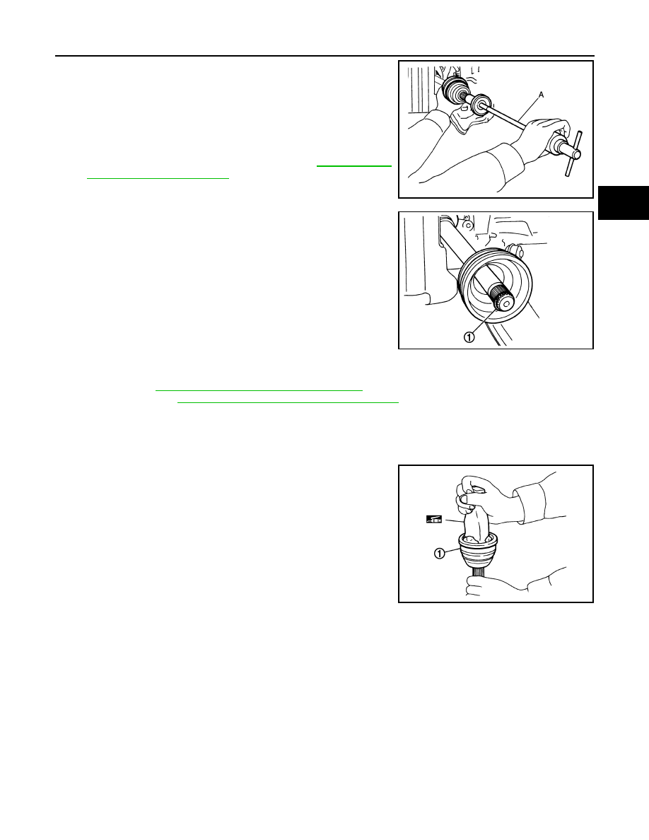
12. Screw drive shaft puller (A) (commercial service tool) into joint
sub-assembly screw part to a length of 30 mm (1.18 in) or more.
Support drive shaft with one hand and pull out joint sub-assem-
bly from shaft.
CAUTION:
• Align drive shaft puller and drive shaft and remove them
by pulling firmly and uniformly.
• If joint sub-assembly cannot be pulled out, try after
removing drive shaft from vehicle. Refer to
.
13. Remove circular clip (1) from shaft.
14. Remove boot from shaft.
Transaxle Side
• Remove boot after removing drive shaft.
FAX-45, "AWD : Removal and Installation"
.
- Disassembly: Refer to
FAX-49, "AWD : Disassembly and Assembly"
.
INSTALLATION
Wheel Side
1. Clean the old grease on joint sub-assembly with paper waste.
2. Fill serration slot joint sub-assembly (1) with NISSAN genuine
grease or equivalent until the serration slot and ball groove
become full to the brim.
CAUTION:
After applying grease, use a paper waste to wipe off old
grease that has oozed out.
3. Install boot and boot bands to shaft.
CAUTION:
• Wrap serration on shaft with tape to protect the boot from damage.
• Never reuse boot and boot band.
4. Remove the tape wrapped around the serration on shaft.
JPDIF0258ZZ
JPDIF0007ZZ
JPDIF0008ZZ