Nissan Juke F15. Manual - part 643


  Index      Nissan     Nissan Juke F15 (2015 year) - Service and Repair Manual


Search            


Content   ..  641  642  643  644   ..


Nissan Juke F15. Manual - part 643


EM-126

< UNIT DISASSEMBLY AND ASSEMBLY >

[MR FOR NISMO RS MODELS]

CYLINDER BLOCK

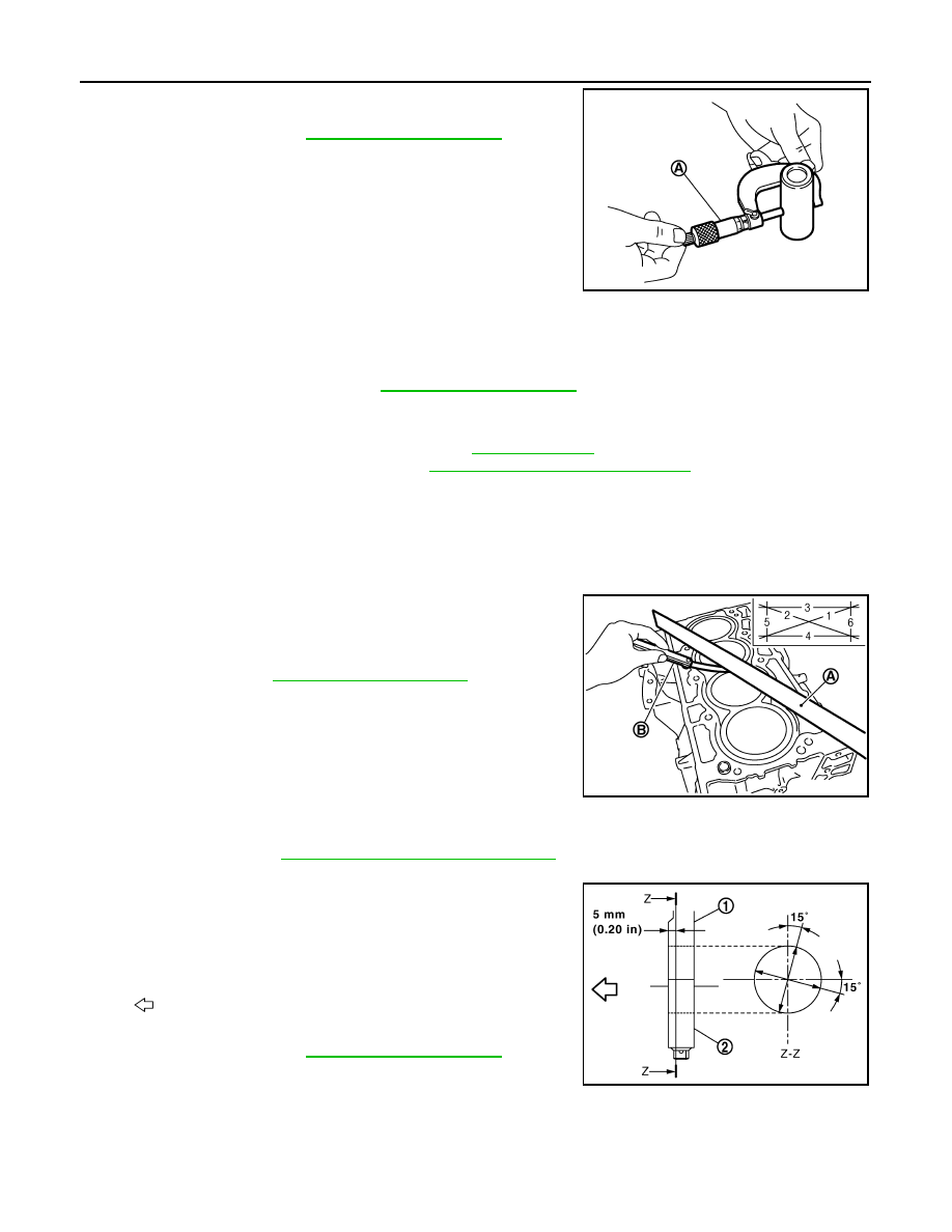
Measure the outer diameter of piston pin with a micrometer (A).

Connecting Rod Bushing Oil Clearance

(Connecting rod bushing oil clearance) = (Connecting rod bushing inner diameter) – (Piston pin outer diame-

ter)

• If the measured value is out of the standard, replace connecting rod assembly and/or piston and piston pin

assembly.

• If replacing piston and piston pin assembly. Refer to 

EM-133, "Piston"

.

• If replacing connecting rod assembly. Refer to 

EM-134, "Connecting Rod Bearing"

.

CYLINDER BLOCK TOP SURFACE DISTORTION

• Using a scraper, remove gasket on the cylinder block surface, and also remove engine oil, scale, carbon, or

other contamination. 

CAUTION:

Be careful not to allow gasket flakes to enter engine oil or engine coolant passages.

• Measure the distortion on the cylinder block upper face at some

different points in six directions with a straight edge (A) and feeler

gauge (B).

• If it exceeds the limit, replace cylinder block.

MAIN BEARING HOUSING INNER DIAMETER

• Install main bearing cap without main bearings installed, and tighten main bearing cap mounting bolts to the

specified torque. Refer to 

EM-115, "Disassembly and Assembly"

.

• Measure the inner diameter of main bearing housing with a bore gauge. 

• Measure the position shown in the figure [5 mm (0.20 in)] back-

ward from main bearing housing front side in the 2 directions as

shown in the figure. The smaller one is the measured value.

• If out of the standard, replace cylinder block and main bearing

caps assembly. 

NOTE:

Main bearing caps cannot be replaced as a single, because it is machined together with cylinder block.

PISTON TO CYLINDER BORE CLEARANCE

Standard : 

Refer 

to 

EM-144, "Cylinder Block"

.

PBIC3266J

Standard and Limit 

: Refer to 

EM-144, "Cylinder Block"

.

Limit : 

Refer 

to 

EM-144, "Cylinder Block"

.

PBIC3250J

1

: Cylinder block

2

: Main bearing cap

: Engine front

Standard : 

Refer 

to 

EM-144, "Cylinder Block"

.

PBIC4005E

CYLINDER BLOCK

EM-127

< UNIT DISASSEMBLY AND ASSEMBLY >

[MR FOR NISMO RS MODELS]

C

D

E

F

G

H

I

J

K

L

M

A

EM

N

P

O

Cylinder Bore Inner Diameter

• Using a bore gauge, measure the cylinder bore for wear, out-of-

round and taper at six different points on each cylinder. [(A) and (B)

directions at (C), (D), and (E)] [(A) is in longitudinal direction of

engine]

NOTE:

When determining cylinder bore grade, measure the cylinder bore

(B) direction at (D) position.

• If the measured value exceeds the limit, or if there are scratches and/or seizure on the cylinder inner wall,

replace cylinder block. 

NOTE:

Oversize piston is not provided.

Piston Skirt Diameter

Measure the outer diameter of piston skirt with a micrometer (A).

Piston to Cylinder Bore Clearance

Calculate by piston skirt diameter and cylinder bore inner diameter

[direction (B), position (D)].

(Clearance) = (Cylinder bore inner diameter) – (Piston skirt diame-

ter)

• If it exceeds the limit, replace piston and piston pin assembly and/or cylinder block. Refer to 

EM-133, "Pis-

ton"

.

f

: 10 mm (0.39 in)

g

: 60 mm (2.36 in)

h

: 130 mm (5.12 in)

Standard:

Cylinder bore inner diameter 

: Refer to 

EM-144, "Cylinder Block"

.

Limit:

Out-of-round [Difference between (A) and (B)]
Taper [Difference between (C) and (D)]

: Refer to 

EM-144, "Cylinder Block"

.

JPBIA2059ZZ

Standard : 

Refer 

to 

EM-144, "Cylinder Block"

.

PBIC3272J

A :  Direction  A
C : Position C
E : Position E
f

: 10 mm (0.39 in)

g

: 60 mm (2.36 in)

h

: 130 mm (5.12 in)

Standard and Limit 

: Refer to 

EM-144, "Cylinder Block"

.

JPBIA2059ZZ

EM-128

< UNIT DISASSEMBLY AND ASSEMBLY >

[MR FOR NISMO RS MODELS]

CYLINDER BLOCK

CRANKSHAFT MAIN JOURNAL DIAMETER

• Measure the outer diameter of crankshaft main journals with a

micrometer (A).

• If out of the standard, measure the main bearing oil clearance.

Then use undersize bearing. Refer to 

EM-148, "Main Bearing"

.

CRANKSHAFT PIN JOURNAL DIAMETER 

• Measure the outer diameter of crankshaft pin journal with a micrometer.

• If out of the standard, measure the connecting rod bearing oil clearance. Then use undersize bearing. Refer

to 

EM-148, "Connecting Rod Bearing"

.

OUT-OF-ROUND AND TAPER OF CRANKSHAFT

• Measure the dimensions at four different points as shown in the

figure on each main journal and pin journal with a micrometer. 

• Out-of-round is indicated by the difference in dimensions between

(X) and (Y) at (A) and (B).

• Taper is indicated by the difference in dimension between (A) and

(B) at (X) and (Y).

• If the measured value exceeds the limit, correct or replace crankshaft.

• If corrected, measure the bearing oil clearance of the corrected main journal and/or pin journal. Then select

main bearing and/or connecting rod bearing. Refer to 

EM-134, "Connecting Rod Bearing"

 and/or 

EM-136,

"Main Bearing"

.

CRANKSHAFT RUNOUT 

• Place a V-block on a precise flat table to support the journals on the both end of the crankshaft.

• Place a dial indicator (A) straight up on the No. 3 journal. 

• While rotating crankshaft, read the movement of the pointer on the

dial indicator. (Total indicator reading)

• If it exceeds the limit, replace crankshaft.

CONNECTING ROD BEARING OIL CLEARANCE

Method by Calculation

Standard : 

Refer 

to 

EM-144, "Cylinder Block"

.

PBIC3457J

Standard : 

Refer 

to 

EM-144, "Cylinder Block"

.

Limit:

Out-of-round [Difference between (X) and (Y)]
Taper [Difference between (A) and (B)]

: Refer to 

EM-144, "Cylinder Block"

.

PBIC3459J

Standard and Limit

: Refer to 

EM-144, "Cylinder 

Block"

.

PBIC3458J

CYLINDER BLOCK

EM-129

< UNIT DISASSEMBLY AND ASSEMBLY >

[MR FOR NISMO RS MODELS]

C

D

E

F

G

H

I

J

K

L

M

A

EM

N

P

O

• Install connecting rod bearings (2) to connecting rod (3) and con-

necting rod bearing cap (1), and tighten connecting rod cap bolts to

the specified torque. Refer to 

EM-115, "Disassembly and Assem-

bly"

• Measure the inner diameter of connecting rod bearing with an

inside micrometer.

(Bearing oil clearance) = (Connecting rod bearing inner diameter)

– (Crankshaft pin journal diameter)

• If clearance exceeds the limit, select proper connecting rod bearing according to connecting rod big end

diameter and crankshaft pin journal diameter to obtain specified bearing oil clearance. Refer to 

EM-134,

"Connecting Rod Bearing"

.

Method of Using Plastigage

• Remove engine oil and dust on crankshaft pin and the surfaces of each bearing completely. 

• Cut a plastigage slightly shorter than the bearing width, and place it in crankshaft axial direction, avoiding oil

holes.

• Install connecting rod bearings to connecting rod and cap, and tighten connecting rod cap bolts to the speci-

fied torque. Refer to 

EM-115, "Disassembly and Assembly"

.

CAUTION:

Never rotate crankshaft.

• Remove connecting rod cap and bearing, and using the scale (A)

on the plastigage bag, measure the plastigage width. 

NOTE:

The procedure when the measured value exceeds the limit is

same as that described in the “Method by Calculation”.

MAIN BEARING OIL CLEARANCE

Method by Calculation

• Install main bearings (3) to cylinder block (1) and main bearing cap

(2), and tighten main bearing cap mounting bolts to the specified

torque. Refer to 

EM-115, "Disassembly and Assembly"

• Measure the inner diameter of main bearing with a bore gauge.

(Bearing oil clearance) = (Main bearing inner diameter) – (Crank-

shaft main journal diameter)

• If clearance exceeds the limit, select proper main bearing according to main bearing inner diameter and

crankshaft main journal diameter to obtain specified bearing oil clearance. Refer to 

EM-136, "Main Bearing"

.

Method of Using Plastigage

• Remove engine oil and dust on crankshaft main journal and the surfaces of each bearing completely. 

• Cut a plastigage slightly shorter than the bearing width, and place it in crankshaft axial direction, avoiding oil

holes.

• Install main bearings to cylinder block and main bearing cap, and tighten main bearing cap mounting bolts to

the specified torque. Refer to 

EM-115, "Disassembly and Assembly"

A

: Example

B

: Inner diameter measuring direction

Standard and Limit  : Refer  to 

EM-148, "Connecting Rod Bearing"

.

PBIC3275J

JPBIA4438ZZ

A

: Example

B

: Inner diameter measuring direction

Standard and Limit : Refer to 

EM-148, "Main Bearing"

.

PBIC3277J


Content   ..  641  642  643  644   ..