Nissan Juke F15. Manual - part 637


  Index      Nissan     Nissan Juke F15 (2015 year) - Service and Repair Manual


Search            


Content   ..  635  636  637  638   ..


Nissan Juke F15. Manual - part 637


EM-102

< UNIT DISASSEMBLY AND ASSEMBLY >

[MR FOR NISMO RS MODELS]

CYLINDER HEAD

• Camshaft: Refer to 

EM-88, "Exploded View"

.

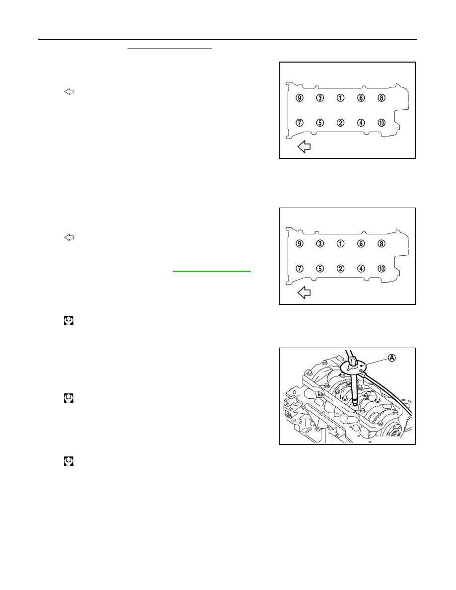
2. Remove cylinder head.

• Loosen cylinder head bolts in reverse order as shown in the

figure. 

• Using TORX socket, loosen cylinder head bolts.

3. Remove cylinder head gasket.

INSTALLATION

1. Install cylinder head gasket.
2. Install cylinder head, and tighten cylinder head bolts in numeri-

cal order as shown in the figure with the following procedure.

CAUTION:

If cylinder head bolts are reused, check their outer diame-

ters before installation. Refer to 

EM-107, "Inspection"

.

a. Apply new engine oil to threads and seating surface of mounting

bolts.

b. Tighten all cylinder head bolts.

c.

Turn all cylinder head bolts 100 degrees clockwise (angle tightening).

CAUTION:

Check and confirm the tightening angle by using an angle

wrench [SST: KV10112100 (BT8653-A)] (A) or protractor.

Never judge by visual inspection without the tool.

d. Completely loosen.

CAUTION:

In this step, loosen cylinder head bolts in reverse order that

indicated in the figure.

e. Tighten all cylinder head bolts.

f.

Turn all cylinder head bolts 95 degrees clockwise (angle tightening).

g. Turn all cylinder head bolts 95 degrees clockwise again (angle tightening).
3. Install in the reverse order of removal, for the rest of parts. 

Disassembly and Assembly

INFOID:0000000012197304

DISASSEMBLY

1. Remove spark plug with spark plug wrench (commercial service tool).
2. Remove valve lifter.

• Identify installation positions, and store them without mixing them up.

: Engine front

JPBIA4415ZZ

: Engine front

: 40.0 N·m (4.1 kg-m, 30 ft-lb)

: 0 N·m (0 kg-m, 0 ft-lb)

: 40.0 N·m (4.1 kg-m, 30 ft-lb)

JPBIA4415ZZ

JPBIA4435ZZ

CYLINDER HEAD

EM-103

< UNIT DISASSEMBLY AND ASSEMBLY >

[MR FOR NISMO RS MODELS]

C

D

E

F

G

H

I

J

K

L

M

A

EM

N

P

O

3. Remove valve collet. 

• Compress valve spring with the valve spring compressor [SST:

KV10116200 (J-26336-A)] (A), the attachment [SST:

KV10115900 (J-26336-20)] (C), and the adapter [SST:

KV10109220 ( — )] (B). Remove valve collet with a magnet

hand.

CAUTION:

• Be careful not to damage valve lifter holes.

• Fit the attachment [SST: KV10115900 (J-26336-20)] in the

center of valve spring retainer to press it.

4. Remove valve spring retainer and valve spring (with valve spring seat).

CAUTION:

Never remove valve spring seat from valve spring.

5. Push valve stem to combustion chamber side, and remove valve. 

• Identify installation positions, and store them without mixing them up.

6. Remove valve oil seal with a valve oil seal puller [SST:

KV10107902 (J-38959)] (A).

7. When valve seat must be replaced.

• Bore out old seat until it collapses. Boring should not continue beyond the bottom face of the seat

recess in cylinder head. Set the machine depth stop to ensure this. Refer to 

EM-142, "Cylinder Head"

.

CAUTION:

Never bore excessively to prevent cylinder head from scratching.

8. When valve guide must be replaced.

JPBIA1365ZZ

1

: Valve spring retainer

A

:  Attachment

JPBIA4477ZZ

PBIC3210J

EM-104

< UNIT DISASSEMBLY AND ASSEMBLY >

[MR FOR NISMO RS MODELS]

CYLINDER HEAD

a. To remove valve guide, heat cylinder head to 110 to 130

°C (230

to 266

°F) by soaking in heated oil (A).

b. Drive out valve guide with a hammer and valve guide drift (com-

mercial service tool).

CAUTION:

Cylinder head contains heat, wear protective equipment to

avoid getting burned.

ASSEMBLY

1. When valve guide is removed, install it. 

CAUTION:

Replace with oversize [0.2 mm (0.008 in)] valve guide.

a. Ream cylinder head valve guide hole with a valve guide reamer

(commercial service tool) (A).

b. Heat cylinder head to 110 to 130

°C (230 to 266°F) by soaking in

heated oil (A).

PBIC3214J

SEM931C

For service parts: Oversize [0.2 mm (0.008 in)] 

Refer to 

EM-142, "Cylinder Head"

.

PBIC3215J

PBIC3214J

CYLINDER HEAD

EM-105

< UNIT DISASSEMBLY AND ASSEMBLY >

[MR FOR NISMO RS MODELS]

C

D

E

F

G

H

I

J

K

L

M

A

EM

N

P

O

c. Press valve guide (1) from camshaft side to dimensions as

shown in the figure.

CAUTION:

Cylinder head contains heat, wear protective equipment to

avoid getting burned.

d. Apply reamer finish to valve guide with a valve guide reamer

(commercial service tool) (A).

2. When valve seat is removed, install it. 

CAUTION:

Replace with oversize [0.5 mm (0.020 in)] valve seat.

a. Ream cylinder head (1) recess diameter for service valve seat

(2).

• Be sure to ream in circles concentric to the valve guide center.

This will enable valve seat to fit correctly.

b. Heat cylinder head to 110 to 130

°C (230 to 266°F) by soaking in

heated oil (A).

c. Provide valve seats cooled well with dry ice. Press-fit valve seat into cylinder head.

CAUTION:

• Never touch cold valve seats directly.

• Cylinder head contains heat, wear protective equipment to avoid getting burned.

2

: Cylinder head

Projection (H)

: Refer to 

EM-142, "Cylinder Head"

.

PBIC3217J

Standard

: Refer to 

EM-142, "Cylinder Head"

.

PBIC3215J

For service parts: Oversize [0.5 mm (0.020 in)]

Refer to 

EM-142, "Cylinder Head"

.

PBIC3218J

PBIC3214J


Content   ..  635  636  637  638   ..