Nissan Juke F15. Manual - part 577
P159C, P159D G SENSOR
EC-1121
< DTC/CIRCUIT DIAGNOSIS >
[MR EXCEPT FOR NISMO RS MODELS]
C
D
E
F
G
H
I
J
K
L
M
A
EC
N
P
O
2.
CHECK G SENSOR SIGNAL CIRCUIT
1. Turn ignition switch OFF.
2. Disconnect ECM harness connector.
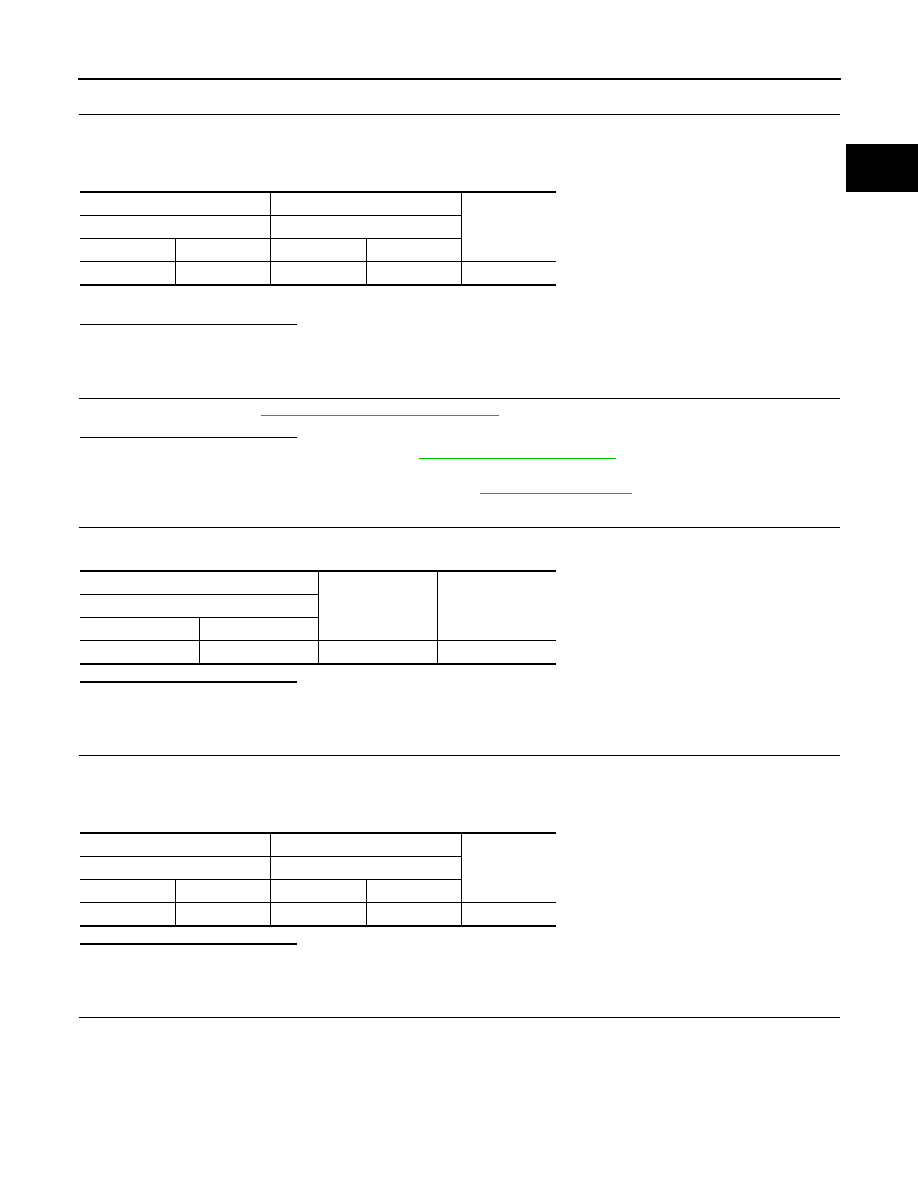
3. Check the continuity between G sensor harness connector and ECM harness connector.
4. Also check harness for short to ground and short to power.
Is the inspection result normal?
YES
>> GO TO 3.
NO
>> Repair or replace error-detected parts.
3.
CHECK G SENSOR
Check G sensor. Refer to
EC-1122, "Component Inspection"
Is the inspection result normal?
YES
>> Check intermittent incident. Refer to
GI-45, "Intermittent Incident"
.
NO
>> 1. Replace G sensor.
2. Perform calibration of G sensor. Refer to
4.
CHECK G SENSOR POWER SUPPLY CIRCUIT-II
Check the voltage between G sensor harness connector terminal and ground.
Is the inspection result normal?
YES
>> GO TO 5.
NO
>> GO TO 7.
5.
CHECK G SENSOR GROUND CIRCUIT
1. Turn ignition switch OFF.
2. Disconnect ECM harness connector.
3. Check the continuity between G sensor harness connector and ECM harness connector.
Is the inspection result normal?
YES
>> GO TO 6.
NO
>> Repair or replace error-detected parts.
6.
CHECK ECM GROUND CIRCUIT
Check the continuity between ECM harness connector and ground.
+
−
Continuity
G sensor
ECM
Connector
Terminal
Connector
Terminal
B32
1
F23
34
Existed
+
−
Voltage
(Approx.)
G sensor
Connector
Terminal
B32
3
Ground
5 V
+
−
Continuity
G sensor
ECM
Connector
Terminal
Connector
Terminal
B32
3
F23
29
Existed