Nissan Juke F15. Manual - part 460


  Index      Nissan     Nissan Juke F15 (2015 year) - Service and Repair Manual


Search            


Content   ..  458  459  460  461   ..


Nissan Juke F15. Manual - part 460


SYSTEM

EC-653

< SYSTEM DESCRIPTION >

[MR EXCEPT FOR NISMO RS MODELS]

C

D

E

F

G

H

I

J

K

L

M

A

EC

N

P

O

NOTE:

MIL turns ON if a malfunction is detected in leak diagnosis results again at the trip after the fuel filler cap warn-

ing display turns ON/OFF.

AUTOMATIC SPEED CONTROL DEVICE (ASCD)
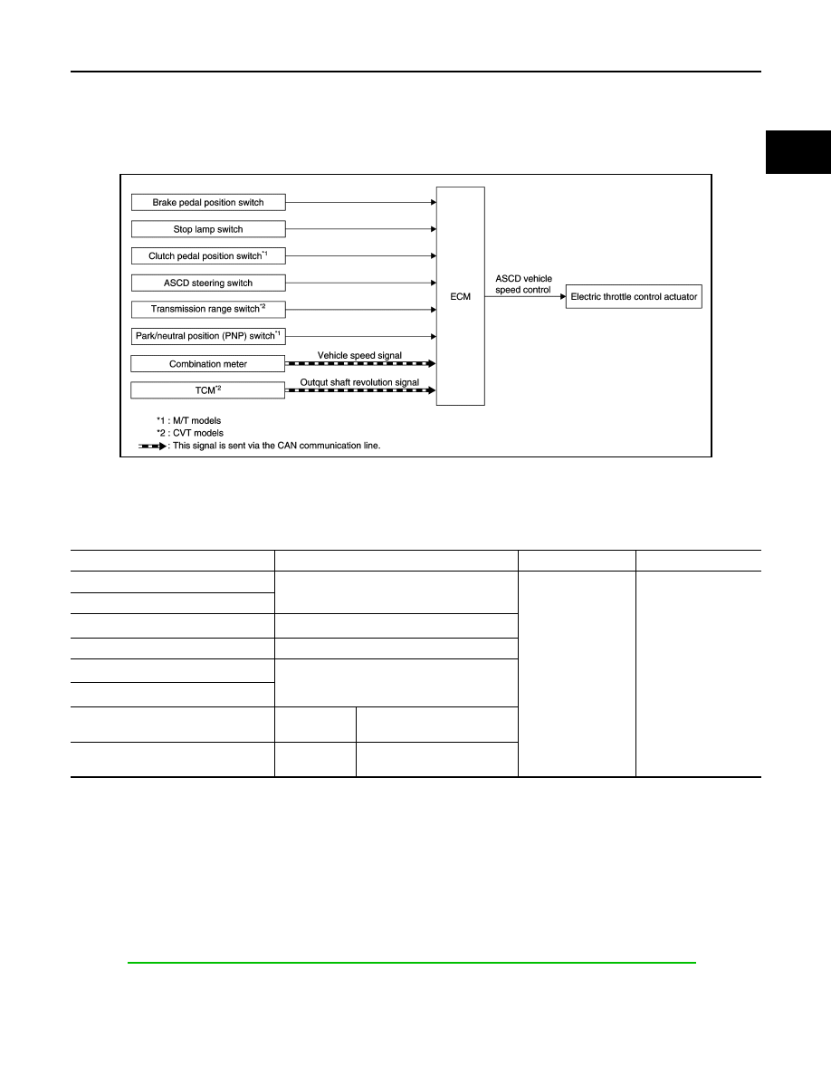
AUTOMATIC SPEED CONTROL DEVICE (ASCD) : System Diagram

INFOID:0000000012198230

AUTOMATIC SPEED CONTROL DEVICE (ASCD) : System Description

INFOID:0000000012198231

INPUT/OUTPUT SIGNAL CHART

*1: M/T models
*2: CVT models

BASIC ASCD SYSTEM

Refer to Owner's Manual for ASCD operating instructions.

Automatic Speed Control Device (ASCD) allows a driver to keep vehicle at predetermined constant speed

without depressing accelerator pedal. Driver can set vehicle speed in advance between approximately 40 km/

h (25 MPH) and 144km/h (90 MPH).

ECM controls throttle angle of electric throttle control actuator to regulate engine speed.

Operation status of ASCD is indicated by CRUISE indicator and SET indicator in combination meter. If any

malfunction occurs in ASCD system, it automatically deactivates control.

Refer to 

EC-656, "AUTOMATIC SPEED CONTROL DEVICE (ASCD) : Switch Name and Function"

 for ASCD

operating instructions.

NOTE:

Always drive vehicle in safe manner according to traffic conditions and obey all traffic laws.

INTEGRATED CONTROL SYSTEM

JPBIA4713GB

Sensor

Input signal to ECM

ECM function

Actuator

Brake pedal position switch

Brake pedal operation

ASCD vehicle speed 
control

Electric throttle control 
actuator

Stop lamp switch

Clutch pedal position switch

*1

Clutch pedal operation

ASCD steering switch

ASCD steering switch operation

Transmission range switch

*2

Gear position

Park/neutral position (PNP) switch

*1

Combination meter

CAN commu-
nication

Vehicle speed signal

TCM

*2

CAN commu-
nication

Output shaft revolution signal

EC-654

< SYSTEM DESCRIPTION >

[MR EXCEPT FOR NISMO RS MODELS]

SYSTEM

INTEGRATED CONTROL SYSTEM : System Diagram

INFOID:0000000012198232

CVT models

M/T models

INTEGRATED CONTROL SYSTEM : System Description

INFOID:0000000012198233

CVT models

System Description

TCM transmits a drive mode select signal to ECM via CAN communication, according to a NORMAL mode

signal, SPORT mode signal, or ECO mode signal received from the multi display unit via CAN communication.

ECM controls torque and throttle opening angle characteristics appropriate for each mode, based on a

received drive mode select signal.

NOTE:

• Because of the multi display unit operation, the display may indicate that the mode is switching. However,

the mode may not actually switch due to CAN communication error.

• When a CAN communication error occurs between ECM and TCM, the mode switches to NORMAL mode.

M/T models

System Description

ECM controls torque and throttle opening angle characteristics appropriate for each mode, based on a NOR-

MAL mode signal, SPORT mode signal, or ECO mode signal received from the multi display unit via CAN

communication.

NOTE:

• Because of the multi display unit operation, the display may indicate that the mode is switching. However,

the mode may not actually switch due to CAN communication error.

JPBIA4714GB

JPBIA4763GB

SYSTEM

EC-655

< SYSTEM DESCRIPTION >

[MR EXCEPT FOR NISMO RS MODELS]

C

D

E

F

G

H

I

J

K

L

M

A

EC

N

P

O

• When a CAN communication error occurs between ECM and the multi display unit, the mode switches to

NORMAL mode.

Control By Mode

CAN COMMUNICATION
CAN COMMUNICATION : System Description

INFOID:0000000012198234

CAN (Controller Area Network) is a serial communication line for real time application. It is an on-vehicle mul-

tiplex communication line with high data communication speed and excellent error detection ability. Many elec-

tronic control units are equipped onto a vehicle, and each control unit shares information and links with other

control units during operation (not independent). In CAN communication, control units are connected with 2

communication lines (CAN H line, CAN L line) allowing a high rate of information transmission with less wiring.

Each control unit transmits/receives data but selectively reads required data only.

Refer to 

LAN-30, "CAN COMMUNICATION SYSTEM : CAN Communication Signal Chart"

, about CAN com-

munication for detail.

Mode

Control

NORMAL mode

Offers a better balance of fuel economy and traveling performance.

SPORT mode

Allows throttle opening angle change and torque control for obtaining reality and acceleration perfor-
mance appropriate to a winding run.

ECO mode

Allows throttle opening angle change and torque control for assisting better fuel efficiency.

EC-656

< SYSTEM DESCRIPTION >

[MR EXCEPT FOR NISMO RS MODELS]

OPERATION

OPERATION

AUTOMATIC SPEED CONTROL DEVICE (ASCD)
AUTOMATIC SPEED CONTROL DEVICE (ASCD) : Switch Name and Function

INFOID:0000000012198235

SWITCHES AND INDICATORS

SET SPEED RANGE

ASCD system can be set the following vehicle speed.

SWITCH OPERATION

SET OPERATION

Press MAIN switch. (The CRUISE indicator in combination meter illuminates.)

When vehicle speed reaches a desired speed between approximately 40 km/h (25 MPH) and 144 km/h (90

MPH), press COAST/SET switch.

ACCELERATE OPERATION

If the ACCEL/RES switch is pressed during the cruise control driving, increase the vehicle speed until the

switch is released or vehicle speed reaches maximum speed controlled by the system.

And then ASCD will keep the new set speed.

CANCEL OPERATION

• When any of following conditions exist, the cruise operation is canceled.

- CANCEL switch is pressed

- ASCD MAIN switch is pressed (Set speed is cleared)

- More than 2 switches at ASCD steering switch are pressed at the same time (Set speed is cleared)

- Brake pedal is depressed

- Clutch pedal is depressed or gear position is changed to neutral position. (M/T models)

- Selector lever is changed to N, P or R position (CVT models)

- Vehicle speed decreased to 13 km/h (8 MPH) lower than the set speed

- TCS system is operated

1.

CRUISE indicator 

2.

CANCEL switch

3.

ACCEL/RES switch

4.

COAST/SET switch

5.

ASCD MAIN switch

A.

On the combination meter

B.

On the steering wheel

JPBIA4897ZZ

Minimum speed (Approx.)

Maximum speed (Approx.)

40 km/h (25 MPH)

144 km/h (90 MPH)

Item

Function

CANCEL switch

Cancels the cruise control driving. 

ACCEL/RES switch

• Resumes the set speed.
• Increases speed incrementally during cruise control driving.

COAST/SET switch

• Sets desired cruise speed.
• Decreases speed incrementally during cruise control driving.

ASCD MAIN switch

Master switch to activate the ASCD system.


Content   ..  458  459  460  461   ..