Nissan Juke F15. Manual - part 451


  Index      Nissan     Nissan Juke F15 (2015 year) - Service and Repair Manual


Search            


Content   ..  449  450  451  452   ..


Nissan Juke F15. Manual - part 451


COMPONENT PARTS

EC-617

< SYSTEM DESCRIPTION >

[MR EXCEPT FOR NISMO RS MODELS]

C

D

E

F

G

H

I

J

K

L

M

A

EC

N

P

O

<Reference data>

*: These data are reference values and are measured between ECM terminals.

Cooling Fan

INFOID:0000000012198181

COOLING FAN CONTROL MODULE

Cooling fan control module receives ON/OFF pulse duty signal from IPDM E/R. Corresponding to this ON/OFF

pulse duty signal, cooling fan control module sends cooling fan motor operating voltage to cooling fan motor.

The revolution speed of cooling fan motor is controlled by duty cycle of the voltage.

COOLING FAN MOTOR

Cooling fan motor receives cooling fan motor operating voltage from cooling fan control module. The revolu-

tion speed of cooling fan motor is controlled by duty cycle of the voltage.

EVAP Canister Purge Volume Control Solenoid Valve

INFOID:0000000012198182

The EVAP canister purge volume control solenoid valve uses a ON/

OFF duty to control the flow rate of fuel vapor from the EVAP canis-

ter. The EVAP canister purge volume control solenoid valve is

moved by ON/OFF pulses from the ECM. The longer the ON pulse,

the greater the amount of fuel vapor that will flow through the valve.

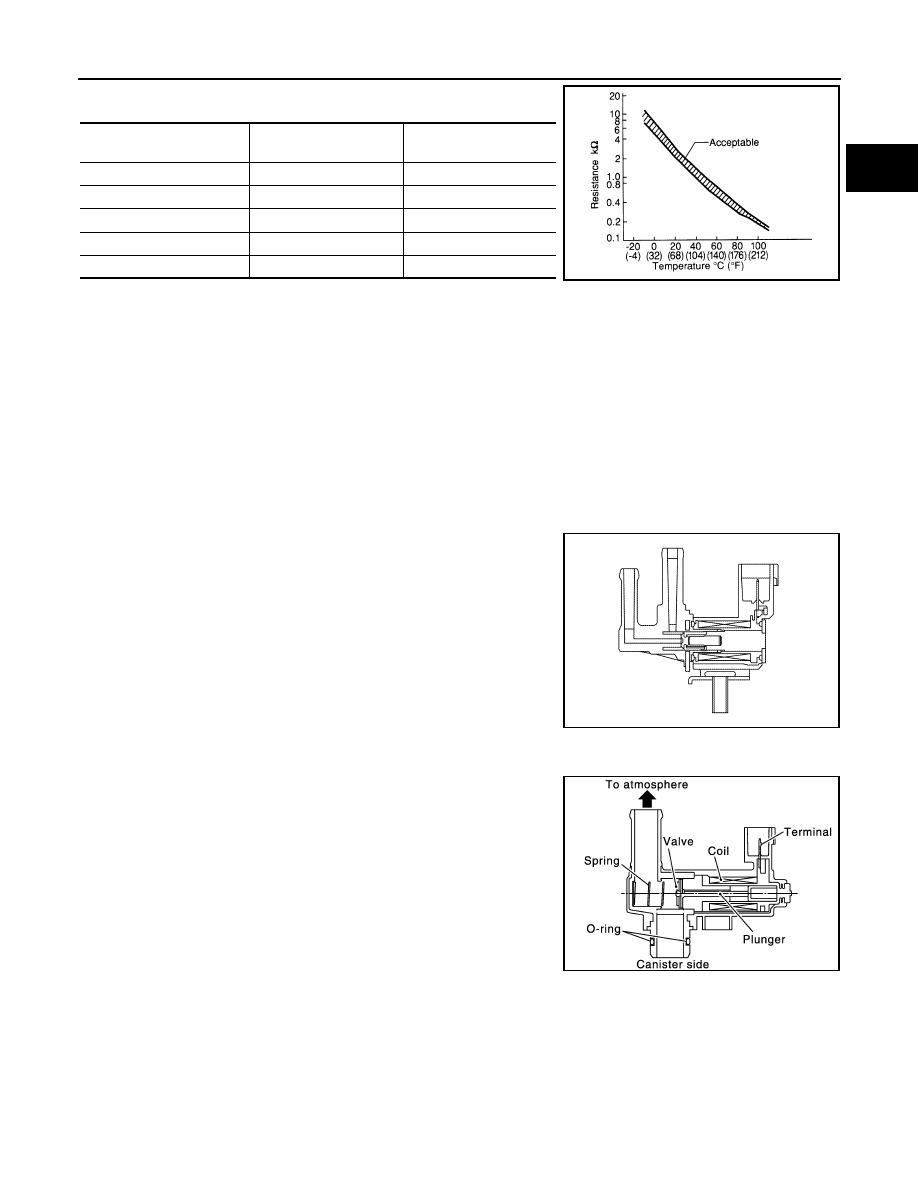
EVAP Canister Vent Control Valve

INFOID:0000000012198183

The EVAP canister vent control valve is located on the EVAP canis-

ter and is used to seal the canister vent.

This solenoid valve responds to signals from the ECM. When the

ECM sends an ON signal, the coil in the solenoid valve is energized.

A plunger will then move to seal the canister vent. The ability to seal

the vent is necessary for the on board diagnosis of other evaporative

emission control system components.

This solenoid valve is used only for diagnosis, and usually remains

opened.

When the vent is closed, under normal purge conditions, the evapo-

rative emission control system is depressurized and allows “EVAP

Control System” diagnosis.

Engine oil temperature

[

°C (°F)]

Voltage

*

 (V)

Resistance (k

Ω)

–10 (14)

4.29-4.50

7.0 - 11.4

20 (68)

3.48-3.58

2.37 - 2.63

50 (122)

2.03-2.49

0.68 - 1.00

90 (194)

0.97-1.04

0.236 - 0.260

110 (230)

0.63-0.67

0.143 - 0.153

SEF012P

JSBIA0651ZZ

PBIB1263E

EC-618

< SYSTEM DESCRIPTION >

[MR EXCEPT FOR NISMO RS MODELS]

COMPONENT PARTS

EVAP Control System Pressure Sensor

INFOID:0000000012198184

The EVAP control system pressure sensor detects pressure in the

purge line. The sensor output voltage to the ECM increases as pres-

sure increases.

Battery Current Sensor (With Battery Temperature Sensor)

INFOID:0000000012198185

OUTLINE

The power generation voltage variable control enables fuel con-

sumption to be decreased by reducing the engine load which is

caused by the power generation of the generator.

Based on sensor signals, ECM judges whether or not the power

generation voltage variable control is performed. When performing

the power generation voltage variable control, ECM calculates the

target power generation voltage based on the sensor signal. And

ECM sends the calculated value as the power generation command

value to IPDM E/R. For the details of the power generation voltage

variable control, refer to

CHG-8, "POWER GENERATION VOLTAGE

VARIABLE CONTROL SYSTEM : System Description"

.

CAUTION:

Never connect the electrical component or the ground wire directly to the battery terminal. The con-

nection causes the malfunction of the power generation voltage variable control, and then the battery

discharge may occur.

BATTERY CURRENT SENSOR

The battery current sensor is installed to the battery negative cable. The sensor measures the charging/dis-

charging current of the battery.

BATTERY TEMPERATURE SENSOR

Battery temperature sensor is integrated in battery current sensor.

The sensor measures temperature around the battery.

The electrical resistance of the thermistor decreases as temperature

increases.

<Reference data>

*: These data are reference values and are measured between battery temperature
sensor signal terminal and sensor ground.

PBIB3370E

JPBIA3262ZZ

Temperature [

°C (°F)]

Voltage

*

 (V)

Resistance (k

Ω)

25 (77)

3.333

1.9 - 2.1

90 (194)

0.969

0.222 - 0.258

SEF012P

COMPONENT PARTS

EC-619

< SYSTEM DESCRIPTION >

[MR EXCEPT FOR NISMO RS MODELS]

C

D

E

F

G

H

I

J

K

L

M

A

EC

N

P

O

Malfunction Indicator lamp (MIL)

INFOID:0000000012198186

Malfunction Indicator lamp (MIL) is located on the combination

meter.

MIL will illuminate when the ignition switch is turned ON without the

engine running. This is a bulb check.

When the engine is started, MIL should turn OFF. If the MIL remains

illuminated, the on board diagnostic system has detected an engine

system malfunction.

For details, refer to 

EC-666, "DIAGNOSIS DESCRIPTION : Malfunc-

tion Indicator Lamp (MIL)"

.

Control modules that a DTC of MIL ON/Blink is stored (Control mod-

ule varies among DTCs.):

• ECM

• TCM

Oil Pressure Warning Lamp

INFOID:0000000012198187

Oil pressure warning lamp is located on the combination meter. 

It indicates the low pressure of the engine oil and the malfunction of

the engine oil pressure system.

Combination meter turns the oil pressure warning lamp ON/OFF

according to the oil pressure warning lamp signal received from

ECM via CAN communication.

For details, refer to 

EC-644, "ENGINE PROTECTION CONTROL AT

LOW ENGINE OIL PRESSURE : System Description"

.

Refrigerant Pressure Sensor

INFOID:0000000012198188

The refrigerant pressure sensor is installed at the condenser of the air conditioner system. The sensor uses an

electrostatic volume pressure transducer to convert refrigerant pressure to voltage. The voltage signal is sent

to ECM, and ECM controls cooling fan system.

Manifold Absolute Pressure Sensor

INFOID:0000000012198189

The manifold absolute pressure (MAP) sensor is placed at intake

manifold collector. It detects intake manifold pressure and sends the

voltage signal to the ECM.

The sensor uses a silicon diaphragm which is sensitive to the

change in pressure. As the pressure increases, the voltage rises.

JSBIA1315ZZ

PBIA8559J

PBIB2657E

JMBIA0877ZZ

EC-620

< SYSTEM DESCRIPTION >

[MR EXCEPT FOR NISMO RS MODELS]

COMPONENT PARTS

Stop Lamp Switch & Brake Pedal Position Switch

INFOID:0000000012198190

Stop lamp switch and brake pedal position switch are installed to brake pedal bracket.

ECM detects the state of the brake pedal by those two types of input (ON/OFF signal).

Clutch Interlock Switch

INFOID:0000000012198191

When the clutch pedal is depressed, the clutch interlock switch turns ON and the clutch interlock switch signal

is sent to the ECM. The ECM judges the clutch pedal conditions via the signal (ON or OFF).

Clutch Pedal Position Switch

INFOID:0000000012198192

When the clutch pedal is depressed, the clutch pedal position switch turns OFF and the clutch pedal position

switch signal is sent to the ECM. The ECM judges the clutch pedal conditions via the signal (ON or OFF).

ASCD Steering Switch

INFOID:0000000012198193

ASCD steering switch has variant values of electrical resistance for each button. ECM reads voltage variation

of switch, and determines which button is operated.

Information Display

INFOID:0000000012198194

The operation mode of the ASCD is indicated on the information display in the combination meter.

ECM transmits the status signal to the combination meter via CAN communication according to ASCD opera-

tion.

Brake pedal

Brake pedal position switch

Stop lamp switch

Released

ON

OFF

Depressed

OFF

ON

Clutch pedal

Clutch interlock switch

Released

OFF

Depressed

ON

Clutch pedal

Clutch pedal position switch

Released

ON

Depressed

OFF


Content   ..  449  450  451  452   ..