Nissan Juke F15. Manual - part 419
P159B G SENSOR
EC-489
< DTC/CIRCUIT DIAGNOSIS >
[MR FOR NISMO RS MODELS]
C
D
E
F
G
H
I
J
K
L
M
A
EC
N
P
O
2. Perform calibration of G sensor. Refer to
7.
CHECK G SENSOR POWER SUPPLY CIRCUIT-II
Check the voltage between G sensor harness connector terminal and ground.
Is the inspection result normal?
YES
>> GO TO 8.
NO
>> GO TO 10.
8.
CHECK G SENSOR GROUND CIRCUIT
1. Turn ignition switch OFF.
2. Disconnect ECM harness connector.
3. Check the continuity between G sensor harness connector and ECM harness connector.
Is the inspection result normal?
YES
>> GO TO 9.
NO
>> Repair or replace error-detected parts.
9.
CHECK ECM GROUND CIRCUIT
Check the continuity between ECM harness connector and ground.
Is the inspection result normal?
YES
>> Check intermittent incident. Refer to
GI-45, "Intermittent Incident"
.
NO
>> Repair or replace error-detected parts.
10.
CHECK SENSOR POWER SUPPLY CIRCUIT
1. Turn ignition switch OFF.
2. Disconnect ECM harness connectors and each sensor harness connectors
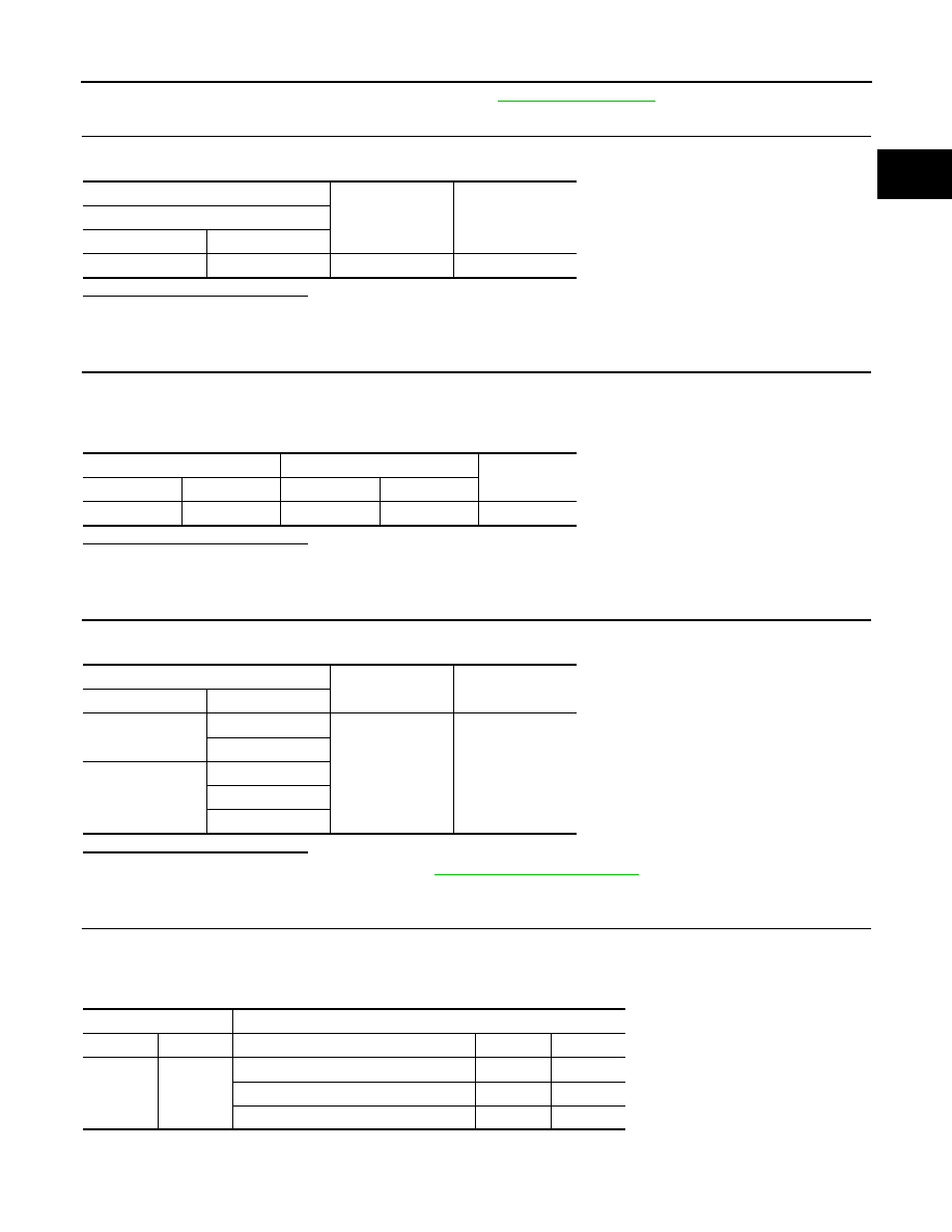
3. Check harness connector for short to power and short to ground, between the following terminals.
+
−
Voltage
(Approx.)
G sensor
Connector
Terminal
B32
3
Ground
5 V
G sensor
ECM
Continuity
Connector
Terminal
Connector
Terminal
B32
2
F26
87
Existed
ECM
Ground
Continuity
Connector
Terminal
F25
1
Ground
Existed
2
E18
123
124
127
ECM
Sensor
Connector
Terminal
Name
Connector
Terminal
F25
39
FRP sensor
F5
1
EOP sensor
F43
3
Turbocharger boost sensor
F75
1