Nissan Juke F15. Manual - part 353


  Index      Nissan     Nissan Juke F15 (2015 year) - Service and Repair Manual


Search            


Content   ..  351  352  353  354   ..


Nissan Juke F15. Manual - part 353


P0090 HIGH PRESSURE FUEL PUMP

EC-225

< DTC/CIRCUIT DIAGNOSIS >

[MR FOR NISMO RS MODELS]

C

D

E

F

G

H

I

J

K

L

M

A

EC

N

P

O

Is inspection result normal?

YES

>> GO TO 10.

NO

>> Replace high pressure fuel pump. Refer to 

EM-49, "Exploded View"

.

10.

CHECK HIGH PRESSURE FUEL PUMP INSTALLATION CONDITION

1. Turn ignition switch OFF.

2. Check that the high pressure fuel pump is installed with no backlash and looseness.
Is the inspection result normal?

YES

>> GO TO 11.

NO

>> Repair or replace error-detected parts.

11.

CHECK CAMSHAFT

1. Remove camshaft. Refer to 

EM-88, "Exploded View"

.

2. Check camshaft. Refer to 

EM-92, "Inspection"

.

Is inspection result normal?

YES

>> Check intermittent incident. Refer to 

GI-45, "Intermittent Incident"

.

NO

>> Replace camshaft. Refer to 

EM-88, "Exploded View"

.

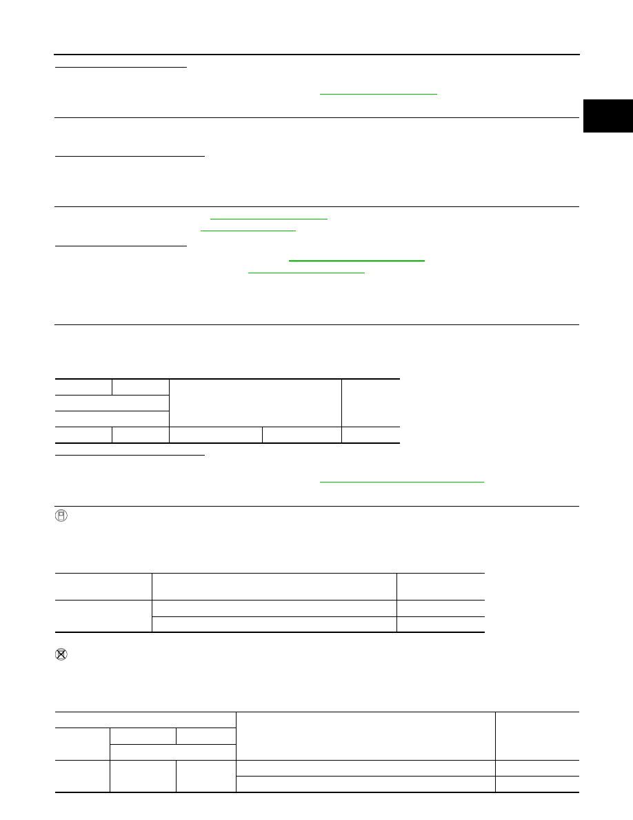
Component Inspection (High Pressure Fuel Pump)

INFOID:0000000012197781

1.

CHECK HIGH PRESSURE FUEL PUMP-1

1. Turn ignition switch OFF.

2. Disconnect high pressure fuel pump harness connector.

3. Check the resistance between high pressure fuel pump terminals.

Is the inspection result normal?

YES

>> GO TO 2.

NO

>> Replace high pressure fuel pump. Refer to 

EM-49, "Removal and Installation"

.

2.

CHECK HIGH PRESSURE FUEL PUMP-2

WITH CONSULT

1. Reconnect high pressure fuel pump harness connector.

2. Start the engine.

3. Check “FUEL PRES SEN V” in “DATA MONITOR” mode of “ECM” using CONSULT.

WITHOUT CONSULT

1. Reconnect high pressure fuel pump harness connector.

2. Start the engine.

3. Check FRP sensor signal voltage.

+

Condition

Resistance

(Approx.)

High pressure fuel pump

Terminal

1

2

Temperature 

°C (°F)

20 – 30 (68 - 86)

0.46 - 0.56 

Monitor item

Condition

Voltage

(Approx.)

FUEL PRES SEN V

Engine speed: idle

1,140 – 1,460 mV

Engine speed: Revving engine from idle to 4,000 rpm quickly

1,140 – 3,060 mV

ECM

Condition

Value

(Approx.)

Connector

+

Terminal

F25

18

44

Engine speed: idle

1,140 – 1,460 mV

Engine speed: Revving engine from idle to 4,000 rpm quickly

1,140 – 3,060 mV

EC-226

< DTC/CIRCUIT DIAGNOSIS >

[MR FOR NISMO RS MODELS]

P0090 HIGH PRESSURE FUEL PUMP

YES

>> INSPECTION END

NO

>> Replace high pressure fuel pump. Refer to 

EM-49, "Removal and Installation"

.

P0096 IAT SENSOR 2

EC-227

< DTC/CIRCUIT DIAGNOSIS >

[MR FOR NISMO RS MODELS]

C

D

E

F

G

H

I

J

K

L

M

A

EC

N

P

O

P0096 IAT SENSOR 2

DTC Logic

INFOID:0000000012197782

DTC DETECTION LOGIC

DTC CONFIRMATION PROCEDURE

1.

INSPECTION START

Is it necessary to erase permanent DTC?

YES

>> GO TO 3.

NO

>> GO TO 2.

2.

PERFORM COMPONENT FUNCTION CHECK

Perform component function check. Refer to 

EC-228, "Component Function Check"

.

NOTE:

Use the component function check to check the overall function of the IAT sensor 2 circuit. During this check,

a 1st trip DTC might not be confirmed.
Is the inspection result normal?

YES

>> INSPECTION END

NO

>> Proceed to 

EC-228, "Diagnosis Procedure"

.

3.

PRECONDITIONING

If DTC CONFIRMATION PROCEDURE has been previously conducted, always perform the following proce-

dure before conducting the next test.

1. Turn ignition switch OFF and wait at least 10 seconds.

2. Turn ignition switch ON.

3. Turn ignition switch OFF and wait at least 10 seconds.

TESTING CONDITION:

• Before performing the following procedure, do not add fuel.

• Before performing the following procedure, check that fuel level is between 1/4 and 4/4.

• Before performing the following procedure, confirm that battery voltage is 11 V or more at idle.

>> GO TO 4.

4.

PERFORM DTC CONFIRMATION PROCEDURE

1. Start engine and let it idle for 60 minutes.

2. Move the vehicle to a cool place.

NOTE:

Cool the vehicle in an environment of ambient air temperature between 

−10°C (14°F) and 35°C (95°F).

3. Turn ignition switch OFF and soak the vehicle for 12 hours.

CAUTION:

Never turn ignition switch ON during soaking.

NOTE:

The vehicle must be cooled with the hood open.

4. Start engine and let it idle for 5 minutes or more.

CAUTION:

Never turn ignition switch OFF during idling.

DTC No.

Trouble diagnosis name

(Trouble diagnosis content)

DTC detecting condition

Possible cause

P0096

IAT SENSOR 2 B1
[Intake air temperature (IAT) 
sensor 2 circuit range/perfor-
mance]

The comparison result of signals transmitted 
to ECM from each temperature sensor (IAT 
sensor 1, IAT sensor 2, ECT sensor, FTT 
sensor, and EOT sensor) shows that the volt-
age signal of the IAT sensor 2 is higher/lower 
than that of other temperature sensors when 
the engine is started with its cold state.

• Harness or connectors

(High or low resistance in the IAT sen-
sor 2 circuit)

• IAT sensor 2

EC-228

< DTC/CIRCUIT DIAGNOSIS >

[MR FOR NISMO RS MODELS]

P0096 IAT SENSOR 2

5. Check 1st trip DTC.
Is 1st trip DTC detected?

YES

>> Proceed to 

EC-228, "Diagnosis Procedure"

.

NO

>> INSPECTION END

Component Function Check

INFOID:0000000012197783

1.

CHECK INTAKE AIR TEMPERATURE (IAT) SENSOR 2

1. Turn ignition switch OFF.

2. Disconnect turbocharger boost sensor harness connector.

3. Check resistance between turbocharger boost sensor terminals as follows.

Is the inspection result normal?

YES

>> Check intermittent incident. Refer to 

GI-45, "Intermittent Incident"

.

NO

>> Proceed to 

EC-228, "Diagnosis Procedure"

.

Diagnosis Procedure

INFOID:0000000012197784

1.

CHECK INTAKE AIR TEMPERATURE (IAT) SENSOR 2

Check intake air temperature sensor 2. Refer to 

EC-228, "Component Inspection"

.

Is the inspection result normal?

YES

>> Check intermittent incident. Refer to 

GI-45, "Intermittent Incident"

.

NO

>> Replace turbocharger boost sensor (with intake temperature sensor 2). Refer to 

EM-32,

"Exploded View"

.

Component Inspection

INFOID:0000000012197785

1.

CHECK INTAKE AIR TEMPERATURE SENSOR 2

1. Turn ignition switch OFF.

2. Disconnect turbocharger boost sensor harness connector.

3. Check resistance between turbocharger boost sensor terminals as follows.

Is the inspection result normal?

YES

>> INSPECTION END

NO

>> Replace turbocharger boost sensor (with intake air temperature sensor 2). Refer to 

EM-29,

"Exploded View"

.

Turbocharger boost sensor

Condition

Resistance (k

Ω)

+

Terminal

3

4

Temperature [

°C (°F)]

25 (77)

1.80 – 2.20

Turbocharger boost sensor

Condition

Resistance (k

Ω)

+

Terminals

3

4

Temperature [

°C (°F)]

25 (77)

1.80 – 2.20


Content   ..  351  352  353  354   ..