Nissan Juke F15. Manual - part 349
P0045, P0047, P0048 TC BOOST CONTROL SOLENOID VALVE
EC-209
< DTC/CIRCUIT DIAGNOSIS >
[MR FOR NISMO RS MODELS]
C
D
E
F
G
H
I
J
K
L
M
A
EC
N
P
O
P0045, P0047, P0048 TC BOOST CONTROL SOLENOID VALVE
DTC Logic
INFOID:0000000012197764
DTC DETECTION LOGIC
DTC CONFIRMATION PROCEDURE
1.
PRECONDITIONING
If DTC Confirmation Procedure has been previously conducted, always perform the following procedure
before conducting the next test.
1. Turn ignition switch OFF and wait at least 10 seconds.
2. Turn ignition switch ON.
3. Turn ignition switch OFF and wait at least 10 seconds.
>> GO TO 2.
2.
PERFORM DTC CONFIRMATION PROCEDURE
1. Turn ignition switch ON and wait at least 5 seconds.
2. Check 1st trip DTC.
Is 1st trip DTC detected?
YES
>> Proceed to
.
NO
>> INSPECTION END
Diagnosis Procedure
INFOID:0000000012197765
1.
CHECK TURBOCHARGER BOOST CONTROL SOLENOID VALVE POWER SUPPLY
1. Turn ignition switch OFF.
2. Disconnect turbocharger boost control solenoid valve harness connector.
3. Turn ignition switch ON.
4. Check the voltage between turbocharger boost control solenoid valve harness connector and ground.
Is the inspection result normal?
YES
>> GO TO 3.
NO
>> GO TO 2.
2.
CHECK TURBOCHARGER BOOST CONTROL SOLENOID VALVE POWER SUPPLY CIRCUIT
1. Turn ignition switch OFF.
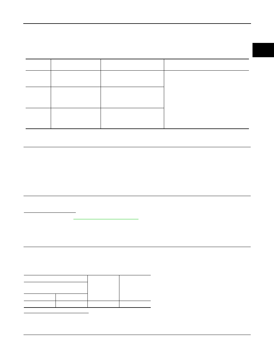
DTC No.
Trouble diagnosis name
(Trouble diagnosis content)
DTC detecting condition
Possible cause
P0045
TC BOOST SOL/V
(Turbocharger boost control
solenoid valve circuit open)
ECM detected the turbocharger
boost control solenoid valve circuit
is open.
• Harness or connectors
(Turbocharger boost control solenoid valve cir-
cuit is open or shorted.)
• Turbocharger boost control solenoid valve
P0047
TC/SC BOOST CONT A
(Turbocharger boost control
solenoid valve circuit low in-
put)
ECM detected the turbocharger
boost control solenoid valve circuit
is short to ground.
P0048
TC/SC BOOST CONT A
(Turbocharger boost control
solenoid valve circuit high
input)
ECM detected the turbocharger
boost control solenoid valve circuit
is short to power.
+
−
Voltage
Turbocharger boost control sole-
noid valve
Connector
Terminal
F54
2
Ground
Battery voltage