Nissan Juke F15. Manual - part 322


  Index      Nissan     Nissan Juke F15 (2015 year) - Service and Repair Manual


Search            


Content   ..  320  321  322  323   ..


Nissan Juke F15. Manual - part 322


ECM

EC-101

< ECU DIAGNOSIS INFORMATION >

[MR FOR NISMO RS MODELS]

C

D

E

F

G

H

I

J

K

L

M

A

EC

N

P

O

*1: Accelerator pedal position sensor 2 signal and throttle position sensor 2 signal are converted by ECM internally. Thus, they differ
from ECM terminals voltage signal.
*2: Before measuring the terminal voltage, confirm that the battery is fully charged. Refer to 

PG-97, "How to Handle Battery"
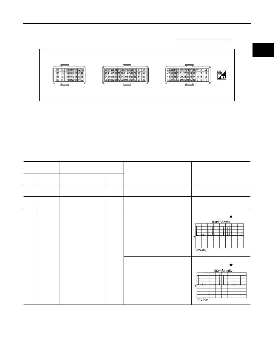
.

TERMINAL LAYOUT

PHYSICAL VALUES

NOTE:

• ECM is located in the engine room left side near battery.

• Connect a break-out box (EG17550000) and harness adapter (EG17550400) between the ECM and ECM

harness connector.

- Use extreme care not to 2 pins at one time.

- Data is for comparison and may not be exact.

• Specification data are reference values and are measured between each terminal and ground.

• Pulse signal is measured by CONSULT.

JSBIA0505ZZ

Terminal No.

(Wire color)

Description

Condition

Value

(Approx.)

+

Signal name

Input/

Output

1

(B)

ECM ground
(Fuel injector)

2

(B)

ECM ground
(Fuel injector)

3

(G)

1

(B)

Fuel injector No. 1, 4 (HI)

Output

[Engine is running]
• Warm-up condition
• Idle speed

NOTE:
The pulse cycle changes depending 
on rpm at idle

BATTERY VOLTAGE

(11 - 14 V) 

4

(Y)

Fuel injector No. 2, 3 (HI)

[Engine is running]
• Engine speed is 2,000 rpm

BATTERY VOLTAGE

(11 - 14 V) 

JPBIA4718ZZ

JPBIA4719ZZ

EC-102

< ECU DIAGNOSIS INFORMATION >

[MR FOR NISMO RS MODELS]

ECM

5

(R)

1

(B)

Fuel injector No. 1 (LO)

Output

[Engine is running]
• Warm-up condition
• Idle speed

NOTE:
The pulse cycle changes depending 
on rpm at idle

BATTERY VOLTAGE

(11 - 14 V) 

6

(BR)

Fuel injector No. 2 (LO)

7

(W)

Fuel injector No. 3 (LO)

[Engine is running]
• Engine speed is 2,000 rpm

BATTERY VOLTAGE

(11 - 14 V) 

8

(R)

Fuel injector No. 4 (LO)

9

(W)

Sensor ground
(Mass air flow sensor, in-
take air temperature 
sensor1)

10

(LG)

Sensor ground
(Engine coolant tempera-
ture sensor)

11

(P)

Sensor ground
(Engine oil temperature 
sensor)

12

(BR)

Sensor ground
(Refrigerant pressure 
sensor, EVAP control sys-
tem pressure sensor)

13

(G)

9

(W)

Mass air flow sensor

Input

[Ignition switch: ON]
• Engine stopped

0.4 V

[Engine is running]
• Warm-up condition
• Idle speed

0.9 - 1.2 V

[Engine is running]
• Warm-up condition
• Engine is revving from idle to about 

4,000 rpm

0.9 - 1.2 to 2.4 V (Check for linear 

voltage rise in response to en-

gine being increased to about 

4,000 rpm.)

14

(L)

10

(LG)

Engine coolant tempera-
ture sensor

Input

[Engine is running]

0 - 4.8 V

Output voltage varies with engine 

coolant temperature.

15

(L)

12

(BR)

EVAP control system 
pressure sensor

Input

[Ignition switch: ON]

0.5 - 4.6 V

17

(Y)

9

(W)

Intake air temperature 
sensor 1

Input

[Engine is running]

0 - 4.8 V

Output voltage varies with intake 

air temperature.

Terminal No.

(Wire color)

Description

Condition

Value

(Approx.)

+

Signal name

Input/

Output

JPBIA4720ZZ

JPBIA4721ZZ

ECM

EC-103

< ECU DIAGNOSIS INFORMATION >

[MR FOR NISMO RS MODELS]

C

D

E

F

G

H

I

J

K

L

M

A

EC

N

P

O

18

(GR)

44

(SB)

Fuel rail pressure sensor

Input

[Engine is running]
• Warm-up condition
• Idle speed

1.14 - 1.46 V

[Engine is running]
• Warm-up condition
• Revving engine from idle to 4,000 

rpm quickly

1.3 - 2.9 V

19

(P)

12

(BR)

Refrigerant pressure sen-
sor

Input

[Engine is running]
• Warm-up condition
• Both A/C switch and blower fan mo-

tor switch: ON (Compressor oper-
ates)

1.0 - 4.0 V

21

(W)

127

(B/Y)

A/F sensor 1

Input

[Ignition switch: ON]

2.2 V

22

(Y)

11

(P)

Engine oil temperature 
sensor

Input

[Engine is running]

0 - 4.8 V

Output voltage varies with engine 

oil temperature.

23

(W)

12

(BR)

Sensor power supply
(Refrigerant pressure 
sensor, EVAP control sys-
tem pressure sensor)

[Ignition switch: ON]

5.0 V

25

(B)

127

(B/Y)

A/F sensor 1

Input

[Engine is running]
• Engine speed is 2,000 rpm

1.8 V

Output voltage varies with air fuel 

ratio.

29

(W)

33

(R)

Heated oxygen sensor 2

Input

[Engine is running]
• Revving engine from idle to 3,000 

rpm quickly after the following condi-
tions are met

- Engine: after warming up
- Keeping the engine speed between 

3,500 and 4,000 rpm for 1 minute 
and at idle for 1 minute under no 
load

0 - 1.0 V

33

(R)

Sensor ground
(Heated oxygen sensor 2)

35

(B)

Sensor ground
(Knock sensor)

36

(W)

35

(B)

Knock sensor

Input

[Engine is running]
• Idle speed

2.5 V

38

(B)

Shield

39

(R)

44

(SB)

Sensor power supply
(Fuel rail pressure sensor, 
turbocharger boost sen-
sor, engine oil pressure 
sensor)

[Ignition switch: ON]

5.0 V

41

(W)

44

(SB)

Turbocharger boost sen-
sor

Input

[Engine is running]
• Warm-up condition
• Idle speed

1.9 V

[Engine is running]
• Warm-up condition
• Engine speed is 2,000 rpm

2.0 V

Terminal No.

(Wire color)

Description

Condition

Value

(Approx.)

+

Signal name

Input/

Output

EC-104

< ECU DIAGNOSIS INFORMATION >

[MR FOR NISMO RS MODELS]

ECM

43

(G)

44

(SB)

Engine oil pressure sen-
sor

Input

[Engine is running]
• Warm-up condition
• Idle speed

1.3 V

[Engine is running]
• Warm-up condition
• Engine speed is 2,000 rpm

2.7 V

44

(SB)

Sensor ground
(Fuel rail pressure sensor, 
turbocharger boost sen-
sor, engine oil pressure 
sensor)

49

(G)

Fuel injector driver power 
supply 1

Input

[Engine is running]
• Warm-up condition
• Idle speed

BATTERY VOLTAGE

(11 - 14 V) 

50

(B)

ECM ground
(High pressure fuel pump)

51

(GR)

127

(B/Y)

Throttle control motor 
(Open)

Output

[Ignition switch: ON]
• Engine stopped
• Selector lever: D (CVT), 1st (M/T) 
• Accelerator pedal: Fully depressed

3.2 V

52

(BR)

127

(B/Y)

Throttle control motor 
(Close)

Output

[Ignition switch: ON]
• Engine stopped
• Selector lever: D (CVT), 1st (M/T) 
• Accelerator pedal: Fully released

1.8 V

53

(BR)

Fuel injector driver power 
supply 2

Input

[Engine is running]
• Warm-up condition
• Idle speed

BATTERY VOLTAGE

(11 - 14 V) 

54

(R)

High pressure fuel pump 
driver power supply

Input

[Engine is running]
• Warm-up condition
• Idle speed

BATTERY VOLTAGE

(11 - 14 V) 

Terminal No.

(Wire color)

Description

Condition

Value

(Approx.)

+

Signal name

Input/

Output

JPBIA3359ZZ

JPBIA3360ZZ

JMBIA0324GB

JMBIA0326GB


Content   ..  320  321  322  323   ..