Content .. 1324 1325 1326 1327 ..
Nissan Juke F15. Manual - part 1326
TM-494
< DTC/CIRCUIT DIAGNOSIS >
[CVT: RE0F10D]
P0826 UP AND DOWN SHIFT SW
NO
>> Repair or replace damaged parts.
7.
CHECK GROUND CIRCUIT
Check continuity between CVT shift selector harness connector terminal and ground.
Is the inspection result normal?
YES
>> Check intermittent incident. Refer to
GI-45, "Intermittent Incident"
.
NO
>> Repair or replace damaged parts.
8.
CHECK PADDLE SHIFTER
1. Turn ignition switch OFF.
2. Disconnect paddle shifter connector.
3. Turn ignition switch ON.
4. Check voltage between paddle shifter side harness connector terminals.
Is the inspection result normal?
YES
>> GO TO 9.
NO
>> GO TO 11.
9.
CHECK PADDLE SHIFTER
Check paddle shifter. Refer to
TM-496, "Component Inspection (Paddle Shifter)"
.
Is the inspection result normal?
YES
>> GO TO 10.
NO
>> Repair or replace damaged parts.
10.
CHECK GROUND CIRCUIT
Check continuity between paddle shifter vehicle side harness connector terminal and ground.
Is the inspection result normal?
YES
>> GO TO 11.
NO
>> Repair or replace damaged parts.
11.
CHECK POWER SOURCE CIRCUIT
Check voltage between paddle shifter vehicle side harness connector terminal and ground.
Is the inspection result normal?
YES
>> GO TO 12.
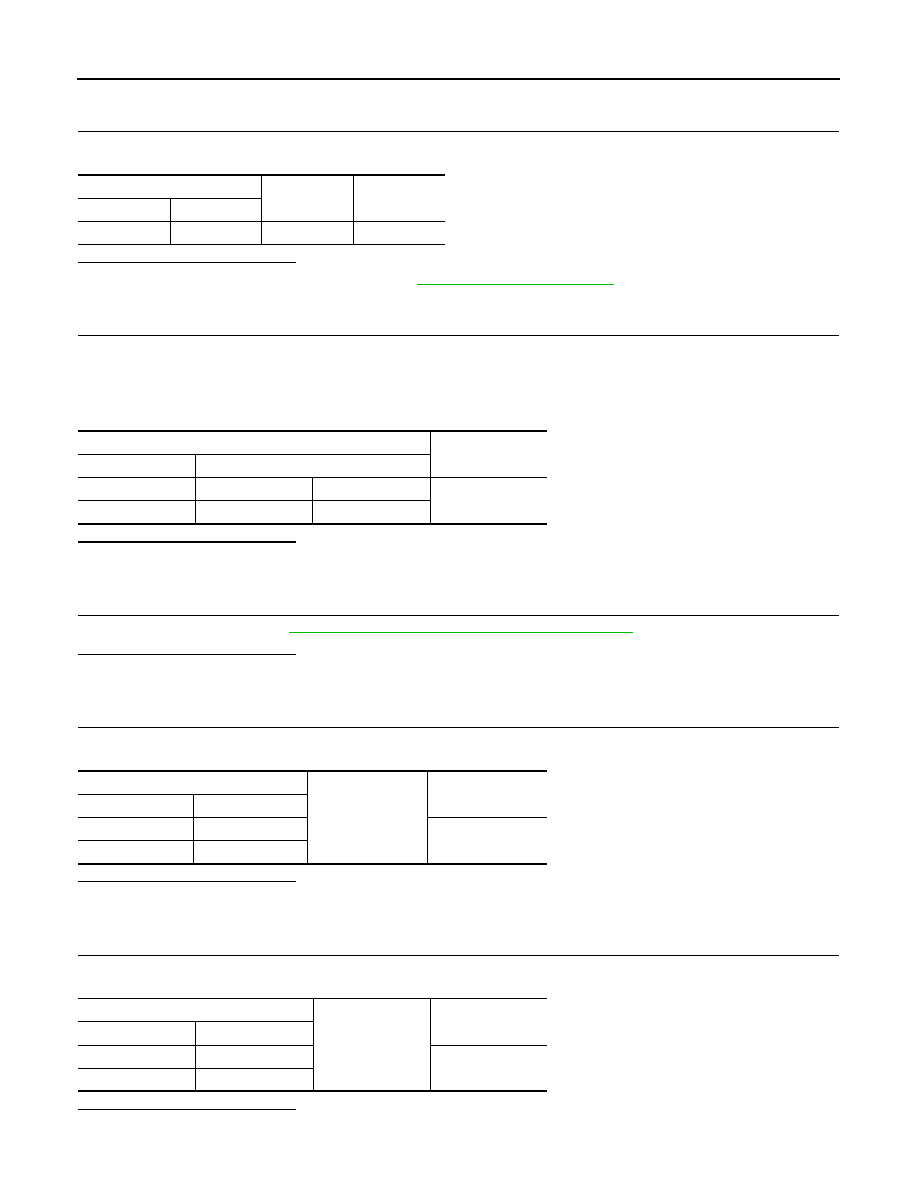
CVT shift selector
—
Continuity
Connector
Terminal
M57
10
Ground
Existed
Paddle shifter
Voltage (Approx.)
Connector
Terminal
M96
3
1
Battery voltage
M97
3
1
Paddle shifter
Ground
Continuity
Connector
Terminal
M96
1
Existed
M97
1
Paddle shifter
Ground
Voltage (Approx.)
Connector
Terminal
M96
3
0 V
M97
3