LG936L Wheel Loader. Manual - part 29
 

  Index      SDLG     LG936L Wheel Loader - service repair manual


Search            


Content   ..  27  28  29  30   ..


LG936L Wheel Loader. Manual - part 29


Operation & Maintenance Manual──LG936L Wheel Loader 

 112

valve, pilot valve, pressure select valve, lift arm cylinder, bucket cylinder, hydraulic pressure oil tank 

and pipe attachments. D32 multi-way valve is a two unit valve. D32A multi-way valve is a three unit 

valve. The bucket unit includes dumping, neutral and receiving bucket in three positions. The 

lift-arms unit controls four actions including floating, lowering, neutral and lifting to utilize the work 

control of loader working device. The third hydraulic function can be reserves.   

The set pressure of the safety valve is 16MPa ~16.5MPa. The overload pressure of the rocker 

cylinder’s large cavity is 18MPa

18.5MPa

 while that of the small cavity is 12MPa. 


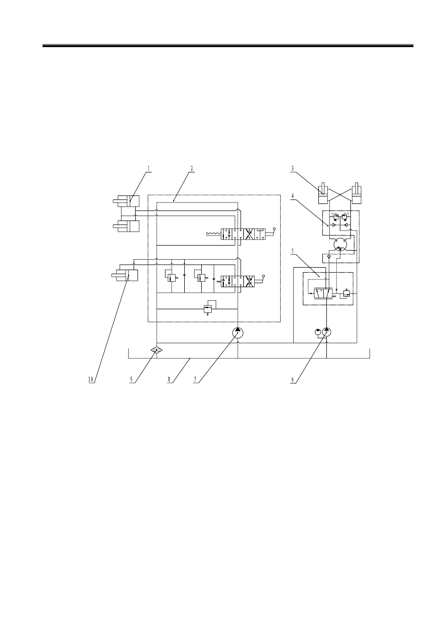
1-Life Arm Cylinder  2-Multi-way Valve  3-Steering cylinder  4-Redirector  5-Priority Valve   

6- Steering and Speed Changing Pump    7-Work Pump  8-Hydraulic Oil Tank   

9-Oil Returning Filter    10- Bucket Cylinder     

Figure 5-2 Mechanical and Manual Control Hydraulic System Diagram 


Operation & Maintenance Manual──LG936L Wheel Loader 

 113

B1

A1

B2

A2

K


1-Work and Pilot Pump    2-Pressure Select Valve  3-Oil Tank  4-Hydraulic Oil Radiator  

  5- Steering and Speed Changing Pump    6-Oil Returning Filter  7-Priority Valve  8-Redirector  

 9- Steering Cylinder  10-Pilot Valve  11-Multi-way Valve  12-Lift Arm Cylinder   

13-Bucket Cylinder  14-Pilot Filter 

Figure 5-3 Two Units Valve Pilot Control Hydraulic System Diagram 


1-Work and Pilot Pump    2- Oil Tank    3- Pressure Select Valve  4-Hydraulic Oil Radiator   

5- Steering and speed changing pump   6-Oil returning filter  7-Priority valve  8-Redirector   

9- Steering Cylinder 10-Pilot Filter    11-Pilot Valve  12-Multi-way Valve  13-Lift-arm Cylinder   

14-Bucket Cylinder


Figure 5-4 Three Units Valve Pilot Control Hydraulic System Diagram 

3 Brake System 

Brake system is used when the machine decelerates, stops or for long-term parking on the level 

ground or slight incline. The brake system of this machine is composed of a driving brake system and 

parking brake system as shown in Figure 5-5,5-6. 

Operation & Maintenance Manual──LG936L Wheel Loader 

 114


1-Parking Brake Air Chamber    2- Brake Magnetic Valve   

3- Combination Valve of Oil Water Separator  4- Air Compressor    5- Air Tank     

6- Air Brake Valve  7- Air Booster Pump 

Figure 5-5 LG36L Single Brake Pedal Braking Diagram 


1- Air Booster Pump  2-Shuttle Valve  3- Air Brake Valve    4- Air Tank 

5- Combination Valve of Oil Water Separator  6- Air Compressor  7- Brake Magnetic Valve 

8- Parking Brake Air Chamber 

Figure 5-6 LG936L Double Brake Pedal Braking Diagram 

3.1 Driving Brake System(Single Brake Pedal):   

As shown in Figure 5-5, this system is the single line, air pushing oil four wheels caliper disk brake 
system.  

Operation & Maintenance Manual──LG936L Wheel Loader 

 115

When the brake pedal is stepped on during driving, the compressed air in air tank 5 flows through air 
brake valve 6 into the air chamber of the air booster valve 7. The compressed air pushes the piston of 
the booster pump to change the oil pressure (oil pressure is about 14MPa). Brake fluid pushes the 
piston of the caliper disk brake and makes the friction disk contact the brake plate to achieve the 
purpose of slowing and braking. 
Release the brake pedal, and the compressed air of the booster pump drains from the brake valve to 
the atmosphere and the brake is released. 

3.2 Driving Brake System(Single Brake Pedal): 

As shown in Figure 5-6, this system is the double brake pedals, air pushing oil four wheels caliper 
disk brake system using two brake calipers for front and back to increase the safety of whole vehicle. 
When the left brake pedal is stepped on during driving, the compressed air in air tank 4 flows through 
air brake valve 3 and shuttle valve 2 into the air chamber of the air booster pump 1. The compressed 
air pushes the piston of the booster pump to change the oil pressure (oil pressure is about 14MPa). 
Brake fluid pushes the piston of the caliper disk brake and makes the friction disk contact with the 
brake plate to achieve the purpose of slowing and braking. The air pressure is outputted at the same 
time to cut off the power of gear box. 
When the right brake pedal is stepped on during driving, the brake principle is the same as left brake 
pedal, but the power of transmission box is not cut off. 

Release the brake pedal, and the compressed air of the booster pump drains from the brake valve to the atmosphere 

and the brake is released.


3.3 Parking Brake System 

This system employs two different forms: the total hydraulic clamping disc braking system and the 

total hydraulic pin steering system. During driving, when the pressure of air in brake system is in 

normal level, rotate the operating button of brake electromagnetic valve slightly, the button will 

bounce out automatically, and then the compress air in the air tank through the brake magnetic valve 

to the parking brake air chamber to pull the plug away and release the brake. When stopping, press 

the operating button of brake magnetic valve, the compress air in the parking brake air chamber 

through the air draining port of brake magnetic valve to aerospace. Then the brake is pulled up under 

the spring to arrive to brake. At the same time, send an electric signal to turn on the parking brake 

indicator, by which to alarm the operator that the vehicle is in the braking condition. 

When the system air pressure is lower than 0.4Mpa, the brake magnetic valve will cut off 
automatically to control the compress air in the parking brake air chamber to drain into the aerospace 
by hand, so that the emergency brake is utilized to protect the safety of vehicle and people. 


Content   ..  27  28  29  30   ..