Mitsubishi Outlander XL. Manual - part 952
 

  Index      Mitsubishi     Mitsubishi Outlander XL - service repair manual 2007 year


Search            copyright infringement  


Content   ..  950  951  952  953   ..


Mitsubishi Outlander XL. Manual - part 952


ZC601710

1

<Front>

<Rear>

12 ± 1 N·m
102 ± 13 in-lb    

3

9.0 ± 1.0 N·m
80 ± 9 in-lb    

Center pillar

Second seat belt

AA00

2

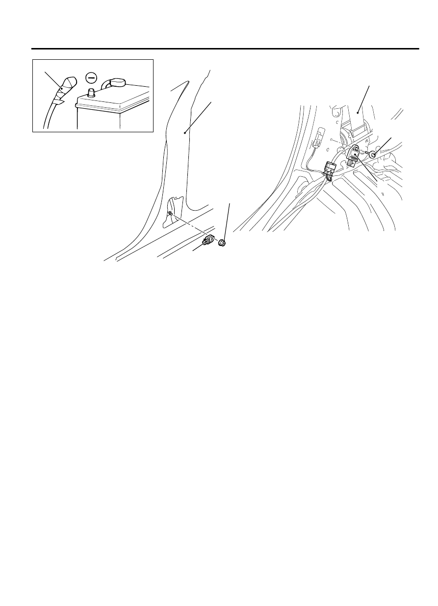
Side impact sensor (front) removal
steps

<<A>>

1.

Negative (-) battery cable connection

·

Center  pillar  trim,  lower  (Refer  to
GROUP 52A, Interior Trim P.52A-10).

·

Seat  belt  with  pre-tensioner  (Refer
to P.52B-345.)

<<B>>

·

Side

 impact

 sensor

 connector

connection

2.

Side impact sensor (Front)
Side

 impact

 sensor

 (front)

installation steps

>>A<<

·

Pre-installation inspection

>>B<<

2.

Side impact sensor (Front)

·

Side

 impact

 sensor

 connector

connection

·

Seat  belt  with  pre-tensioner  (Refer
to P.52B-345.)

·

Center  pillar  trim,  lower  (Refer  to
GROUP 52A, Interior Trim P.52A-10).

1.

Negative (-) battery cable connection

Side

 impact

 sensor

 (front)

installation steps

>>C<<

·

Post-installation inspection
Side impact sensor (Rear) removal
steps

<<A>>

1.

Negative (-) battery cable connection

·

Quarter trim, lower (Refer to GROUP
52A, Interior Trim P.52A-10.)

<<B>>

·

Side

 impact

 sensor

 connector

connection

3.

Side impact sensor (Rear)
Side

 impact

 sensor

 (Rear)

installation steps

>>A<<

·

Pre-installation inspection

>>B<<

3.

Side impact sensor (Rear)

·

Side

 impact

 sensor

 connector

connection

·

Quarter trim, lower (Refer to GROUP
52A, Interior Trim P.52A-10).

1.

Negative (-) battery cable connection

>>C<<

·

Post-installation inspection


NOTE: 

The illustration above shows the side

impact sensor (RH). The position of the side
impact sensor (LH) is symmetrical to this.

SUPPLEMENTAL RESTRAINT SYSTEM (SRS)

52B-339

SIDE IMPACT SENSOR

REMOVAL SERVICE POINT

<<A>> NEGATIVE (-) BATTERY CABLE DISCONNECTION

Wait  at  least  60  seconds  after  disconnecting  the  battery
cable before doing any further work (Refer to P.52B-28
).

Battery  posts,  terminals  and  related  accessories  contain
lead  and  lead  compounds.  WASH  HANDS  AFTER
HANDLING.

ZC500608

Battery

Insulating tape

0000

Battery cable

Disconnect the negative (-) battery cable from the battery and
tape the terminal to prevent accidental connection and air bag
deployment.


<<B>> IMPACT SENSOR CONNECTOR REMOVAL

ZC601568

Side impact sensor

Outer housing of the  
impact sensor connector

0000

Slide the outer housing of the impact sensor connector in the
arrow direction shown, and disconnect the connector.

NOTE: 

The illustration shows the side impact sensor (rear).

As for the impact sensor (front), follow the same procedure.

INSTALLATION SERVICE POINTS

>>A<< PRE-INSTALLATION INSPECTION
Check the side impact sensor for dents, breakage and bending
and measure the resistance between the terminals, even when
installing a new side impact sensor.

>>B <<SIDE IMPACT SENSOR INSTALLATION

If  the  side  impact  sensor  is  not  installed  securely  and
correctly, the side-airbag may not operate normally.
Securely connect the connector.

52B-340

SUPPLEMENTAL RESTRAINT SYSTEM (SRS)

SIDE IMPACT SENSOR


>>C<< POST-INSTALLATION INSPECTION

ZC601295

SRS Warning light

0000

1.

Reconnect the negative (-) battery cable.

2.

Turn the ignition switch to the "ON" position.

3.

Does  the  "SRS"  warning  light  illuminate  for  approximately
seven seconds, and go out?

4.

If yes, the SRS system is functioning properly. If not, refer
to P.52B-33.

INSPECTION

M15204000047USA0000010000

If a dent, crack, deformation or rust is detected,
replace with a new sensor.

NOTE: 

For checking of the side impact sensor

other than described below, refer to the section
concerning SRS diagnosis (Refer to ).

1.

Check  the  side  impact  sensor  and  bracket  for
dents, cracks or deformation.

2.

Check the connector for damage, and terminals for
deformation.

3.

Check that there is no bending or corrosion in the
center pillar.

CURTAIN AIR BAG MODULE

REMOVAL AND INSTALLATION

M15204000135USA0000010000

Never  attempt  to  disassemble  or  repair  the
curtain air bag modules. If faulty, replace it.

Do not drop the curtain air bag modules or clock
spring or allow contact with water, grease or oil.
Replace it if a dent, crack, deformation or rust is
detected.

Do  not  expose  the  curtain  air  bag  modules  to
temperatures over 93°C (200°F).

Wear gloves and safety glasses when handling
air bags that have already deployed.

An undeployed curtain air bag module should
only  be  disposed  of  in  accordance  with  the
procedures (Refer to P.52B-352
).

When  removing  and  installing  the  front
passenger seat, be sure to carry out accuracy
check occupant classification sensor after the
seat  has  been  installed  in  the  vehicle.  (On-
vehicle Service P.52B-322
.)


Pre-removal Operation

Turn the ignition switch to the "LOCK" (OFF) position.

SUPPLEMENTAL RESTRAINT SYSTEM (SRS)

52B-341

SIDE IMPACT SENSOR

ZC601569

2

3

1

AA00

7.0 ± 3.0 N·m
62 ± 27 in-lb    

7.0 ± 3.0 N·m
62 ± 27 in-lb    

Removal steps

<<A>>

1. Negative (-) battery cable connection
·

Headlining  (Refer  to  GROUP  52A,
Headlining P.52A-15).

<<B>>

2. Curtain  air  bag  module  connector

connection

<<C>>

3. Curtain air bag module

INSTALLATION STEPS

>>A<< ·

Pre-installation inspection

INSTALLATION STEPS

>>B<< 3. Curtain air bag module
>>C<< 2. Curtain  air  bag  module  connector

connection

·

Headlining  (Refer  to  GROUP  52A,
Headlining P.52A-15).

1. Negative (-) battery cable connection

>>D<< ·

Post-installation inspection

REMOVAL SERVICE POINTS

<<A>> NEGATIVE (-) BATTERY CABLE DISCONNECTION

ZC500608

Battery

Insulating tape

0000

Battery cable

Wait  at  least  60  seconds  after  disconnecting  the  battery
cable before doing any further work. (Refer to P.52B-28).

Battery  posts,  terminals  and  related  accessories  contain
lead  and  lead  compounds.  WASH  HANDS  AFTER
HANDLING.
Disconnect the negative (-) battery cable from the battery and
tape the terminal to prevent accidental connection and seat belt
pre-tensioner operation.


52B-342

SUPPLEMENTAL RESTRAINT SYSTEM (SRS)

CURTAIN AIR BAG MODULE


Content   ..  950  951  952  953   ..