Mitsubishi Outlander XL. Manual - part 809
 

  Index      Mitsubishi     Mitsubishi Outlander XL - service repair manual 2007 year


Search            copyright infringement  


Content   ..  807  808  809  810   ..


Mitsubishi Outlander XL. Manual - part 809


DISASSEMBLY SERVICE POINT

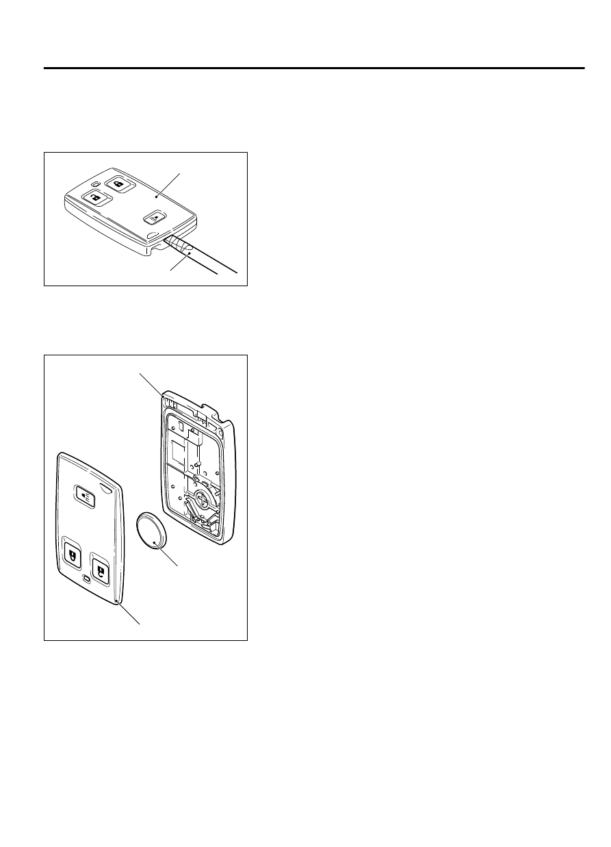
<<A>> UPPER COVER/BATTERY/LOWER COVER
REMOVAL

ZC600222

Flat-tipped screwdriver

Upper cover

0000

Place a flat-tipped screwdriver wrapped with protective tape as
shown  in  the  figure,  and  lever  the  keyless  operation  key  to
remove.

ASSEMBLY SERVICE POINT

>>A<< BATTERY INSTALLATION

ZC600347

+

Battery

Upper cover

Lower cover

0000

Install  a  new  battery  with  the  positive  side  facing  toward  the
lower cover.

Replacement battery: Coin-type lithium battery CR2032

KEYLESS OPERATION SYSTEM (KOS)

42B-179

KEYLESS OPERATION KEY

INSPECTION

M14209100041USA0000010000

KEYLESS OPERATION KEY BATTERY CHECK

AC004486

Measure the voltage of the battery. If the voltage of the battery
is lower than the standard value, replace the battery.

Standard value:2.5 - 3.2 V

TPMS TRANSMITTER

REMOVAL AND INSTALLATION

M14209100164USA0000010000

Ensure valve cap is always in place except when
adjusting tire pressure.

If the valve core and valve cap are replaced, use
a genuine replacement part. The valve core is
similar  to  a  conventional  one,  but  uses  nickel
plating to avoid corrosion.

Replace  the  valve  stem  grommet  and  washer
with a new one every five years or when the tire
is replaced.

Do not drop the TPMS transmitter from height
greater than 1 meter (3.3 feet).

Do  not  expose  the  TPMS  transmitter  to
extraneous magnetic fields.

TPMS  transmitter  should  not  be  stored  at
temperatures above 80°C (176°F).

TPMS  transmitter  should  not  be  exposed  to
temperatures above 100°C (212°F).

If  the  TPMS  transmitter  is  replaced,  execute
"Tire Pressure Sensor ID Registration" on scan
tool MB99158 "Special Function."

Pre-removal Operation

Wheel and Tire Removal

Post-installation Operation

Wheel and Tire Installation

Tire Pressure Sensor ID Registration If a new TPMS transmitter is installed (Refer to P.42B-172.)

After the tire pressure sensor ID registration, check that the TPMS warning light does not illuminate

or flash.

42B-180

KEYLESS OPERATION SYSTEM (KOS)

KEYLESS OPERATION KEY

ZC6045420000

1

2

3

4

N

8.0 ± 0.5 N·m 
71 ± 4 in-lb

0.25 N·m 
2.5 in-lb

5

REMOVAL STEPS

<<A>>

1.

VALVE CAP

<<A>>

2.

VALVE NUT

·

LET  TPMS  TRANSMITTER
FALL INTO TIRE

·

TIRE BEAD

<<B>>

3.

TPMS TRANSMITTER

<<C>>

4.

GROMMET

<<C>>

5.

WASHER
INSTALLATION STEPS

>>A<<

5.

WASHER

INSTALLATION STEPS

>>A<<

4.

GROMMET

>>A<<

3.

TPMS TRANSMITTER

>>A<<

2.

VALVE NUT

>>B<<

·

TIRE BEAD MOUNTING

>>C<<

·

TIRE PRESSURE INFLATION

>>C<<

·

VALVE NUT RETIGHTENING

1.

VALVE CAP

REMOVAL SERVICE POINTS

<<A>> VALVE CAP/VALVE NUT REMOVAL

Ensure valve cap is always in place except when adjusting
tire pressure.

1.

Remove the valve cap.

2.

Rotate tire so that valve stem is in the 6 o’clock position.

3.

Use a long-reach 17.2 mm (0.68 inch) socket to unscrew the
valve nut and remove it. Slowly push valve stem into tire so
that tire pressure is released.

4.

Once tire pressure is released, let TPMS transmitter into tire.

KEYLESS OPERATION SYSTEM (KOS)

42B-181

TPMS TRANSMITTER

<<B>> TPMS TRANSMITTER REMOVAL

ZC6008320000

TPMS  
Transmitter

1.

Place  on  tire  changing  machine  and  break  both  tire  beads
ensuring that the transmitter remains in the bottom of the tire.

Be careful not to damage the TPMS transmitter.

2.

Lubricate tire well and remove outer side of the tire.

3.

Reach inside the tire and remove the TPMS transmitter.

4.

Remove tire from rim using proper tire changing equipment
procedures.


<<C>> GROMMET/WASHER REMOVAL

Do not vary the angle of valve except at mounting on the
rim.  If  varying  the  angle  over  and  over,  it  may  cause
breakage  of  antenna  plate  resulting  in  the  failure  of
transmitter.

Use  a  soft  tool  to  remove  the  grommet  and  washer  to
prevent scratching the valve of the TPMS transmitter.

Remove the grommet and washer from the TPMS transmitter.

INSTALLATION SERVICE POINTS

>>A<< GROMMET/WASHER/TPMS TRANSMITTER/VALVE
NUT INSTALLATION

When installing a new grommet and washer, make sure to
support the valve stem base with a thumb so that there is
no  movement  of  the  stem.  Otherwise,  the  stem  may
protrude resulting in the breakage of antenna plate.

1.

Install a new grommet and washer to the TPMS transmitter.

ZC6045430000

TPMS transmitter

Grommet

Valve nut

Holes

Washer

Visually check that TPMS transmitter is not deformed or
damaged.

When  installing  the  TPMS  transmitter,  be  sure  the  rim,
grommet and valve nut are clean.

Ensure  the  grommet  is  located  inside  the  valve  hole
before installing the valve nut.

While  installing  the  valve  nut,  push  the  transmitter  to
maintain the lower lip of the transmitter case is in contact
with the rim without clearance.

While  installing  the  valve  nut,  ensure  the  tool  is  kept
aligned to the valve and the valve hole.

After installing the valve nut, check that the grommet is
compressed and washer is bend.

42B-182

KEYLESS OPERATION SYSTEM (KOS)

TPMS TRANSMITTER


Content   ..  807  808  809  810   ..