Mitsubishi Outlander XL. Manual - part 746
 

  Index      Mitsubishi     Mitsubishi Outlander XL - service repair manual 2007 year


Search            copyright infringement  


Content   ..  744  745  746  747   ..


Mitsubishi Outlander XL. Manual - part 746


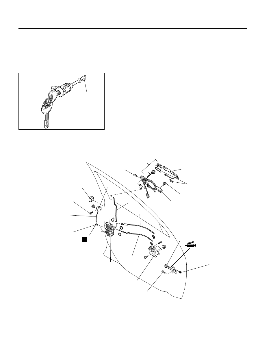
When the door lock key cylinder is replaced by the
key  set  (A)  in  the  figure,  register  the  encrypted
code of the bar code attached to the ignition key.
Refer  to  GROUP  42B,  ID  Code  Registration
Criteria  Table  P.42B-12the 
 vehicle  with  KOS,  or
GROUP  42C,  ID  Code  Registration  Criteria
Table P.42C-8vehicles without KOS.

0000

(B)

Door lock key 
cylinder

ZC600090

When the door lock key cylinder is replaced by the
key  set  (B)  in  the  figure,  do  not  register  the
encrypted  code  of  the  bar  code  attached  to  the
ignition key. If the encrypted code is registered,
the engine cannot start.

Pre-removal operation

Door  trim  assembly  removal  (Refer  to  GROUP  52A,  Door

Trim P.52A-11).

Post-installation operation

Door inside handle play check (Refer to P.42Ab-93).

Door outside handle play check (Refer to P.42Ab-92).

Door trim assembly installation (Refer to GROUP 52A, Door

Trim P.52A-11.)

ZC600091

1

2

5

4

3

6

7

8

9

10

11

12

13

15

16

N

14

0000

<Front door>

25 ± 4 N·m
19 ± 3 ft-lb

7.0 ± 2.0 N·m
43 ± 17 in-lb

4.0 ± 2.0 N·m
35 ± 17 in-lb

4.0 ± 2.0 N·m
35 ± 17 in-lb

4.0 ± 2.0 N·m
35 ± 17 in-lb

5.0 ± 1.0 N·m
44 ± 9 in-lb

DOOR

42Ab-103

DOOR HANDLE AND LATCH

ZC600092

1

7

0000

Door inside handle removal

>>B<<

1.

Door inside handle
Door  lock  key  cylinder  and  door
outside handle removal steps

·

Rear  lower  sash  (Refer  to  P.
42Ab-110.)

2.

Plug

3.

Door  outside  handle  cover  assembly
driver's seat only

4.

Door  lock  key  cylinder  driver's  seat
only

5.

Door outside handle cover

6.

Door outside handle

7.

Door outside handle gasket

8.

Door outside handle base
Door handle and door latch removal
steps

·

Rear  lower  sash  (Refer  to  P.
42Ab-110.)

Door handle and door latch removal
steps

9.

Screw

10. Door latch assembly
11. Inside lock cable
12. Inside handle cable
13. Outside handle rod
14. Front door outside lock rod
15. Front door panel bracket

Door check removal steps

·

Front door speaker (Refer to GROUP
54A, Speaker P.54B-170.)

>>A<<

16. Door check

42Ab-104

DOOR

DOOR HANDLE AND LATCH

ZC600093

1

4

5

6

9

10

11

12

0000

7

N

3

<Rear door>

8

2

25 ± 4 N·m
19 ± 3 ft-lb

7.0 ± 2.0 N·m
43 ± 17 in-lb

4.0 ± 2.0 N·m
35 ± 17 in-lb

4.0 ± 2.0 N·m
35 ± 17 in-lb

5.0 ± 1.0 N·m
44 ± 9 in-lb

ZC600092

1

5

0001

Door inside handle removal

>>B<<

1.

Door inside handle
Door  lock  key  cylinder  and  door
outside handle removal steps

·

Rear  lower  sash  (Refer  to  P.
42Ab-110.)

2.

Plug

3.

Door outside handle cover

4.

Door outside handle

5.

Door outside handle gasket

6.

Door outside handle base
Door handle and door latch removal
steps

·

Rear  lower  sash  (Refer  to  P.
42Ab-110.)

Door handle and door latch removal
steps

7.

Screw

8.

Door latch assembly

9.

Inside lock cable

10. Inside handle cable
11. Outside handle rod

Door check removal steps

·

Rear door speaker (Refer to GROUP
54A , Speaker P.54B-170.)

>>A<<

12. Door check

DOOR

42Ab-105

DOOR HANDLE AND LATCH

INSTALLATION SERVICE POINTS

>>A<< DOOR CHECK INSTALLATION

ZC6000940000

Identification mark

Install  the  door  check  with  the  following  identification  marks
facing upward.

Applicable location

Identification
mark

Front door

Left door

55L

Right door 55R

Rear door

Left door

58L

Right door 58R

>>B<< DOOR INSIDE HANDLE INSTALLATION
When  connecting  the  inside  cable  to  the  door  inside  handle,
ensure that the door latch and the inside handle are unlocked.

INSPECTION

M14203000047USA0000010000

FRONT DOOR LOCK ACTUATOR CHECK

4

2
5

3
6

1

4

2
5

3
6

1

ZC600095

B

A

0000

Lever

UNLOCK

<Front left side>

<Front right side>

LOCK

View A

Lever

UNLOCK

LOCK

View B

ACTUATOR OPERATION CHECK

Lever
position

Battery
connection

Lever
operation

At

 the

"LOCK"
position

Connect  terminal
No.4

 to

 the

negative  battery
terminal.

Connect  terminal
No.6

 to

 the

positive  battery
terminal.

The lever moves
from the "LOCK"
position  to  the
"UNLOCK"
position.

At

 the

"UNLOCK"
position

Connect  terminal
No.6

 to

 the

negative  battery
terminal.

Connect  terminal
No.4

 to

 the

positive  battery
terminal.

The lever moves
from

 the

"UNLOCK"
position  to  the
"LOCK"
position.

ACTUATOR SWITCH CHECK <DRIVER'S SIDE>

Lever position Terminal

number

Normal value

LOCK

2 - 3

Continuity  exists
(2 Ω or less)

42Ab-106

DOOR

DOOR HANDLE AND LATCH


Content   ..  744  745  746  747   ..