Mitsubishi Outlander XL. Manual - part 712
 

  Index      Mitsubishi     Mitsubishi Outlander XL - service repair manual 2007 year


Search            


Content   ..  710  711  712  713   ..


Mitsubishi Outlander XL. Manual - part 712


ZC5018470000

4

11

13

16

10

2

9

8

6

5

7

3

1

16

2

11

13

10

3

9

8

6

5

7

3

4

3

15

14

12

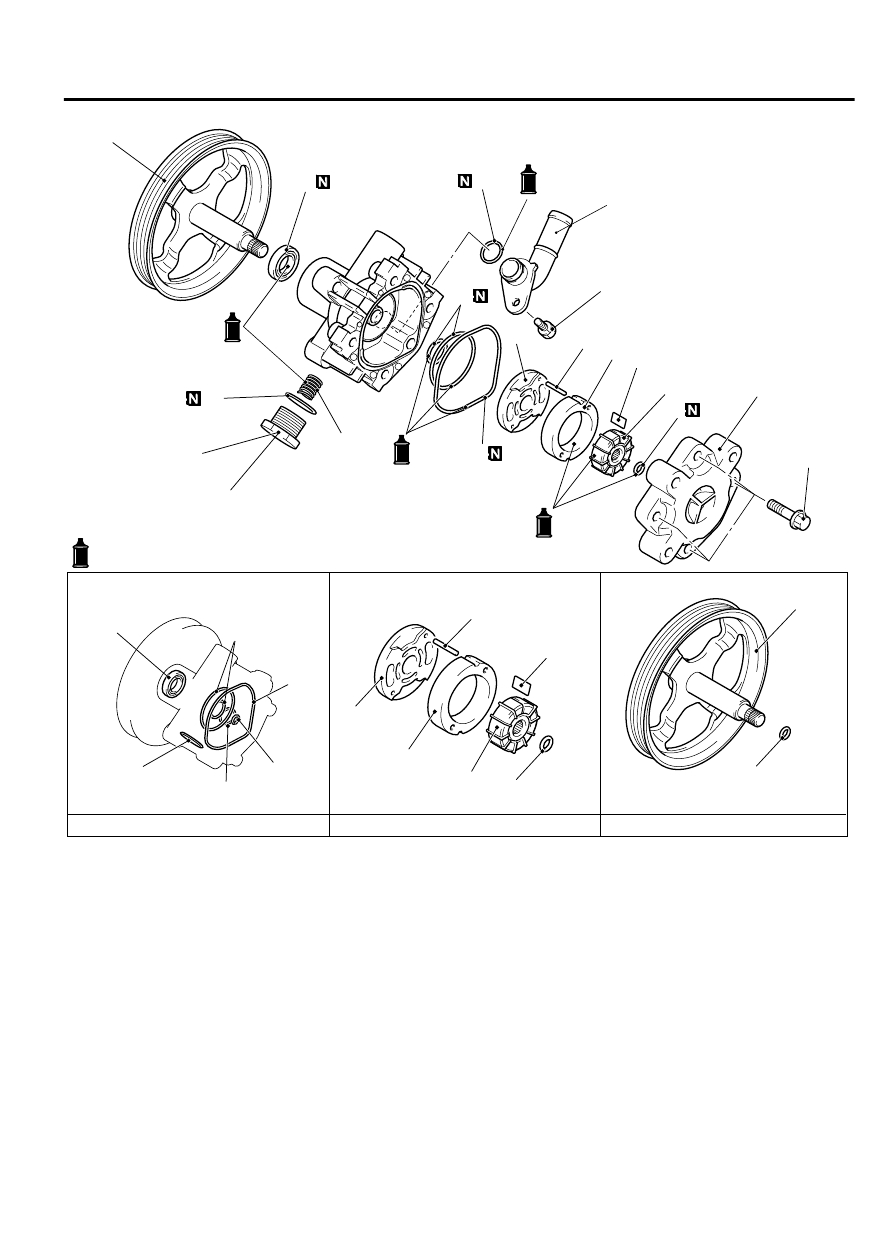
Oil pump seal kit

: ATF DEXRON III


or DEXRON II

Oil pump cartridge kit

Oil pump pulley and shaft kit

28 ± 1 N·m 
21 ± 2 ft-lb

12 ± 1 N·m 
102 ± 11 in-lb

54 ± 14 N·m 
39 ± 10 ft-lb

DISASSEMBLY STEPS

1.

Pump cover

2.

O-ring

3.

Snap ring

4.

Pulley and shaft

5.

Vanes

>>C<< 6.

Cam ring

7.

Rotor

8.

Pin

9.

Side plate

DISASSEMBLY STEPS

>>A<< 10.

O-ring

>>B<< 11.

Oil seal

12.

Plug assembly

>>A<< 13.

O-ring

14.

Flow control spring

15.

Suction connector

>>A<< 16.

O-ring

Required Special Tools:

MB990938: Bar (Snap-in type)

MB991203: Oil Seal and Bearing Installer

POWER STEERING

37-37

POWER STEERING OIL PUMP ASSEMBLY

ASSEMBLY SERVICE POINTS

>>A<< O-RING INSTALLATION

ZC5018480000

1

3

2

Suction connector

Plug assembly

Side plate

NO.

ID × WIDTH mm (in)

1

15.8 × 2.4 (0.62 × 0.09)

2

14.8 × 1.9 (0.58 × 0.07)

3

21.0 × 1.9 (0.83 × 0.07)


>>B<< OIL SEAL INSTALLATION

ZC501935 0000

MB990938

MB991203

Use the following special tools to install the oil seal.

Installer bar (MB990938) [Including in the bearing and oil seal
installer set (MB990925)]

Oil seal and bearing installer (MB991203)


>>C<< CAM RING INSTALLATION

Be sure to install the cam ring in the correct direction as
shown.

37-38

POWER STEERING

POWER STEERING OIL PUMP ASSEMBLY

ZC501936 0000

Side plate side

Pump cover side

Install the cam ring as shown in the illustration.

INSPECTION

M13702000055USA0000010000

Check the pulley and shaft for wear or damage.

Check the rotor and vane groove for "stepped" wear.

Check the contact surface of cam ring and vanes for "stepped"
wear.

Check the vanes for damage.

POWER STEERING HOSES

REMOVAL AND INSTALLATION

M13702000057USA0000010000

Pre-removal operation

Power Steering Fluid Draining (Refer to P.37-17.)

Engine  room  Under  Cover  Front,  Engine  room  Side  Cover,

Engine room Under Cover Rear Removal (Refer to GROUP

51A - Under Cover Removal and Installation P.51A-18.)

Propeller  Shaft  Assembly  Removal  (Refer  to  GROUP  25  -

Propeller Shaft Removal and Installation P.25-5.) <AWD>

Front Exhaust Pipe Removal (Refer to GROUP 15 - Exhaust

Pipe And Main Muffler Removal and Installation P.15-16.)

Front  Roll  Stopper  And  Centermember  Assembly  Removal

(Refer to GROUP 32 - Engine Roll Stopper and Centremember

Removal and Installation P.32-6.)

Post-installation operation

Front Roll Stopper And Centermember Assembly Installation

(Refer to GROUP 32 - Engine Roll Stopper and Centremember

Removal and Installation P.32-6.)

Front Exhaust Pipe Installation (Refer to GROUP 15 - Exhaust

Pipe And Main Muffler Removal and Installation P.15-16.)

Propeller Shaft Assembly Installation (Refer to GROUP 25 -

Propeller Shaft Removal and Installation P.25-5.) <AWD>

Engine  room  Under  Cover  Front,  Engine  room  Side  Cover,

Engine room Under Cover Rear Installation (Refer to GROUP

51A - Under Cover Removal and Installation P.51A-18.)

Power  Steering  Fluid  Refilling  and  Bleeding  (Refer  to  P.

37-17.)

POWER STEERING

37-39

POWER STEERING OIL PUMP ASSEMBLY

ZC5018490000

1

3

9

13

12

16

15

14

10

11

8

6

4

2

5

N

7

N

N

13 ± 2 N·m 
110 ± 22 in-lb

13 ± 2 N·m 
110 ± 22 in-lb

13 ± 2 N·m 
110 ± 22 in-lb

5 ± 2 N·m 
44 ± 17 in-lb

13 ± 2 N·m 
110 ± 22 in-lb

57 ± 7 N·m 
42 ± 5 ft-lb

57 ± 7 N·m 
42 ± 5 ft-lb

15 ± 3 N·m 
11 ± 2 ft-lb

28 ± 2 N·m 
20 ± 2 ft-lb

13 ± 2 N·m 
110 ± 22 in-lb

Heat 
protector

Removal steps

1.

Oil reservoir

2.

Suction hose

3.

Power steering oil pressure sensor

4.

Eye bolt A

5.

Gasket A

6.

Eye bolt B

7.

Gasket B

<<A>>

·

Heat protector

<<A>>

8.

Pressure hose assembly

Removal steps

9.

Return hose C

10. Return tube assembly G
11. Gasket C

>>A<<

12. Return hose G1

<<A>>

>>A<<

13. Return tube C
14. Hose bracket
15. Return hose G2
16. Return tube G

REMOVAL SERVICE POINTS

<<A>> PRESSURE HOSE ASSEMBLY, RETURN TUBE B
REMOVAL
Remove the heat protector, and push the engine assembly and
transaxle assembly toward the front of the vehicle to widen the
clearance. Then, remove the pressure hose assembly and the
return tube B.

37-40

POWER STEERING

POWER STEERING HOSES


Content   ..  710  711  712  713   ..