Mitsubishi Outlander XL. Manual - part 708
 

  Index      Mitsubishi     Mitsubishi Outlander XL - service repair manual 2007 year


Search            


Content   ..  706  707  708  709   ..


Mitsubishi Outlander XL. Manual - part 708


ZC5018330000

5

1

9

9

6

7

11

7

2

3

4

1

11

8

10

N

Claw

Claw

Claw

Claw

<Vehicles without remote 
controlled audio switch>

<Vehicles with remote 
controlled audio switch>

2.5 ± 0.5 N·m 
22.1 ± 4.4 in-lb

9.5 ± 2.5 N·m 
84 ± 22 in-lb

9.5 ± 2.5 N·m 
84 ± 22 in-lb

44 ± 11 N·m 
33 ± 8 ft-lb

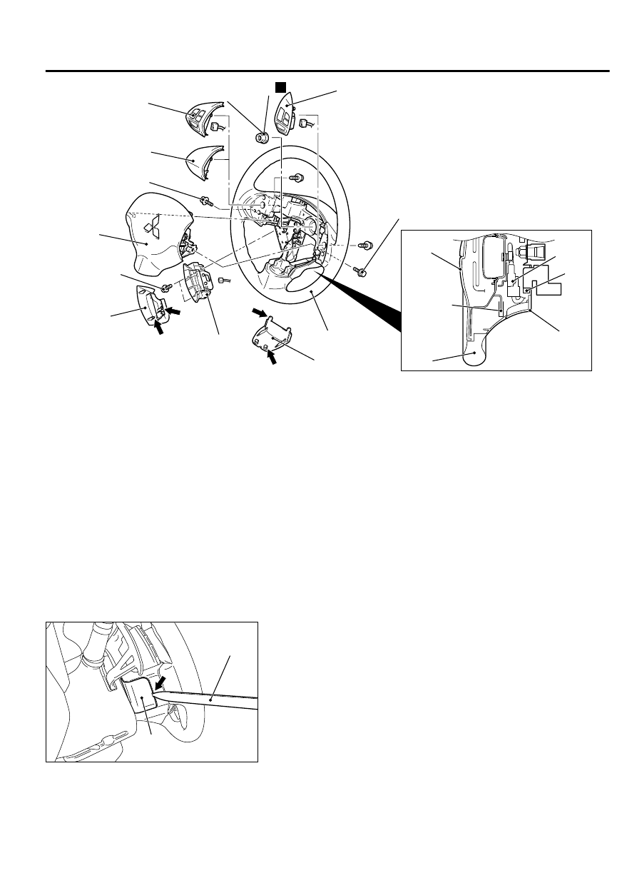
Removal steps

<<A>>

1.

Cover

>>B<<

2.

Horn connector connection

>>B<<

3.

Audio  control  switch  connector
connection  <Vehicles  with  audio
control switch>

<<B>>

>>B<<

4.

Air bag module connector connection

5.

Telematic cover

6.

Telematic switch

Removal steps

<<C>>

7.

Air bag module

8.

Cruise control switch

9.

Bezel  switch  or  Remote  controlled
radio switch

10. Self-locking nut

<<D>>

>>A<<

11. Steering wheel assembly

Required Special Tools:

MB990784: Ornament Remover

MB990803: Steering wheel puller

REMOVAL SERVICE POINTS

<<A>> COVER REMOVAL

ZC501834

Cover

0000

MB990784

Insert  the  special  tool  MB990784  at  the  indicated  position  to
remove the cover.

NOTE: 

The special tool MB990784 can be inserted through the

notch behind the area shown.


POWER STEERING

37-21

STEERING WHEEL

<<B>> AIR BAG MODULE ASSEMBLY CONECTOR
DISCONNECTION

ZC601709

AC600868

Outer housing of the driver’s air bag  
module connector

Horn connector

Lower column cover

0000

Driver’s air bag  
module connector
(4-pin, yellow)

Slide the outer housing of the driver's air bag module connector
in the arrow direction shown, and disconnect the connector.


<<C>> AIR BAG MODULE REMOVAL

Never  use  an  electric  tester  to  diagnose  the  air  bag
module circuit. Never attempt to disassemble the air bag
module.

Be sure to store the removed air bag module in a clean
and dry place with a pad surface facing upward.


<<D>> STEERING WHEEL ASSEMBLY REMOVAL

1.

Position the steering wheel in a straight ahead direction.

Use the special tool to remove the steering wheel since the
steering  column  collision  absorbing  mechanism  may  be
damaged.

37-22

POWER STEERING

STEERING WHEEL

ZC501836

MB990784

0000

2.

Use special tool MB990803 to remove the steering wheel

INSTALLATION SERVICE POINTS

>>A<< STEERING WHEEL ASSEMBLY INSTALLATION
After centering the clock spring (Refer to GROUP 52B - Air Bag
Module  Clock  Spring  P.52B-329.),  install  the  steering  wheel
assembly.

>>B<< AIR BAG MODULE CONNECTOR CONNECTION/
AUDIO CONTROL SWITCH CONNECTOR CONNECTION/
HORN CONNECTOR CONNECTION
Connect the connector securely and route the harnesses not to
lie off the cover hole.

STEERING SHAFT

REMOVAL AND INSTALLATION

M13702000115USA0000010000

Before  removing  the  steering  wheel/air  bag
module assembly, refer to GROUP 52B - Service
Precautions  P.52B-28and 
 Air  Bag  Module
Clock Spring P.52B-329.

After the installation, perform a calibration for
the ASC-ECU to learn the steering wheel sensor
neutral point. (Refer to GROUP 35C, On-vehicle
Service - Steering Wheel Sensor Calibration P.
35C-192.)

Pre-removal operation

Air  Bag  Module  and  Steering  Wheel  Assembly
Removal (Refer to P.37-20.)

Bottom Cover Assembly (Driver’s seat) and Side
Lower  Panel  Assembly  Removal  (Refer  to
GROUP  52A  -  Instrument  Panel  Assembly
Removal and Installation P.52A-2.)

Lower side cover (L) Removal (Refer to GROUP
52A  -  Front  Floor  Console  Assembly  Removal
and Installation P.52A-8.)

WCM  vehicles  with  WCM/Receiver  Antenna
Module  vehicles  with  KOS  Removal  (Refer  to
GROUP  54Ag,  Ignition  Switch  -  On-vehicle
Service  -  Ignition  Switch  Removal  and
Installation P.54Ag-13.)

Post-installation operation

WCM  vehicles  with  WCM/Receiver  Antenna
Module vehicles with KOS Installation (Refer to
GROUP  54Ag,  Ignition  Switch  -  On-vehicle
Service  -  Ignition  Switch  Removal  and
Installation P.54Ag-13.)

Lower  side  cover  (L)  Installation  (Refer  to
GROUP  52A  -  Front  Floor  Console  Assembly
Removal and Installation P.52A-8.)

Bottom Cover Assembly (Driver’s seat) and Side
Lower  Panel  Assembly  Installation  (Refer  to
GROUP  52A  -  Instrument  Panel  Assembly
Removal and Installation P.52A-2.)

Air  Bag  Module  and  Steering  Wheel  Assembly
Installation (Refer to P.37-20.)

POWER STEERING

37-23

STEERING SHAFT

Confirm that the steering wheel is at the straight-
ahead position.

Steering  wheel  sensor  calibration  (Refer  to
GROUP  35C,  On-vehicle  Service  -  Steering
Wheel Sensor Calibration P.35C-192.)

ZC5018370000

A

A

5

9

3

2

6

7

1

8

4

10

Section A-A

Claw

Column 
Cover

2.5 ± 0.5 N·m 
22.1 ± 4.4 in-lb

2.5 ± 0.5 N·m 
22.1 ± 4.4 in-lb

2.5 ± 0.5 N·m 
22.1 ± 4.4 in-lb

7.0 ± 3.0 N·m 
61 ± 26 in-lb

12 ± 3 N·m 
102 ± 26 in-lb

20 ± 5 N·m 
15 ± 3 ft-lb

28 ± 7 N·m 
21 ± 5 ft-lb

Removal steps

<<A>>

1.

Knob cap <Vehicles with KOS>

2.

Ignition key cover

3.

Steering column lower cover

4.

Steering column protector

5.

Steering column upper cover

6.

Paddle  shift  assembly  vehicles  with
paddle shift

>>B<<

7.

Steering  wheel  sensor/clock  spring
column  switch  assembly  (Refer  to
GROUP  35C  -  Steering  Angle
Sensor P.35C-198and GROUP 52B -
Driver  side·passenger  side  air  bag
module clock spring P.52B-329.)

Removal steps

8.

Key interlock cable (Refer to GROUP
23A - A/T Key Interlock And Shiftlock
Mechanisms P.23A-168.)

<<B>>

9.

Steering shaft cover

<<C>>

>>A<<

10. Steering column shaft assembly

37-24

POWER STEERING

STEERING SHAFT


Content   ..  706  707  708  709   ..