Mitsubishi Outlander XL. Manual - part 606
 

  Index      Mitsubishi     Mitsubishi Outlander XL - service repair manual 2007 year


Search            


Content   ..  604  605  606  607   ..


Mitsubishi Outlander XL. Manual - part 606


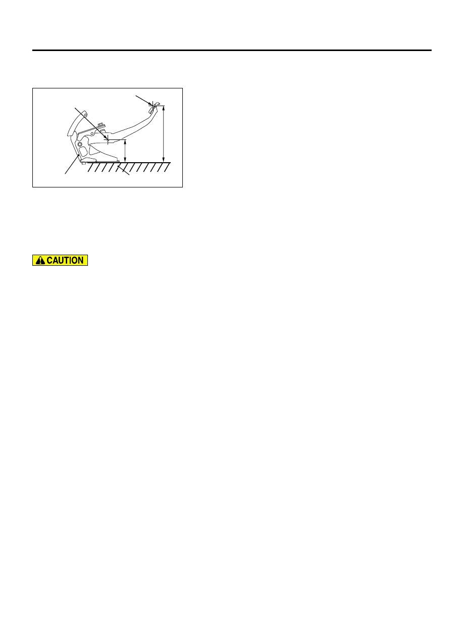
BRAKE PEDAL DISTORTION CHECK

M13501000903USA0000010000

ZC6010260000

97 mm 
(3.82 inch)

A

Brake pedal assembly

Pin assembly
center hole

Pedal pad surface

Flat surface

1.

Place the brake pedal assembly on a level surface as shown
in the figure, and set the distance from the center of the pin
assembly mounting hole to the level surface to 97 mm (3.82
inch). Make sure that the dimension A in the figure (distance
from the pedal pad surface to the level surface) is within the
standard value.

Standard value (A): 250 - 254 mm (9.8 - 10.0 inch)

2.

When dimension A is not within the standard value, replace
the brake pedal assembly.

MASTER CYLINDER ASSEMBLY AND BRAKE BOOSTER

REMOVAL AND INSTALLATION

M13501000037USA0000010001

Do not touch the push rod in the brake booster
because it is already adjusted.

Pre-removal operation

Brake fluid draining

Bottom  Cover  Assembly  (driver's  seat)  Removal  (Refer  to

GROUP 52A - Instrument Panel Assembly P.52A-2).

Strut  Tower  Bar  Removal  (Refer  to  GROUP  42Aa  -  Strut

Tower Bar P.42Aa-11).

Air  Cleaner  Body  Removal  (Refer  to  GROUP  15  -  Air

Cleaner P.15-6).

Post-installation operation

Air  Cleaner  Body  Installation  (Refer  to  GROUP  15  -  Air

Cleaner P.15-6).

Brake fluid refilling and air bleeding (Refer to P.35A-18).

Strut  Tower  Bar  Installation  (Refer  to  GROUP  42Aa  -  Strut

Tower Bar P.42Aa-11).

Bottom  Cover  Assembly  (driver's  seat)  Installation  (Refer  to

GROUP 52A - Instrument Panel Assembly P.52A-2).

BASIC BRAKE SYSTEM

35A-25

BRAKE PEDAL

ZC601801AA00

14 ± 3 N·m
124 ± 26 in-lb

16 ± 3 N·m 
12 ± 2 ft-lb

13 ± 2 N·m 
111 ± 22 in-lb

N

1

2

8

7

5

6

4

3

3

9

10

12

13

15

17

16

14

11

N

Removal steps

1.

Brake fluid level switch connector

2.

Reservoir cap

3.

Brake pipe connection

4.

Master cylinder mounting nuts

5.

Reservoir  assembly  and  master
cylinder assembly

6.

Torx bolt

7.

Reservoir assembly

8.

Master cylinder assembly

9.

O-ring

Removal steps

>>B<<

10. Vacuum hose
11. Clamp

>>B<<

12. Check valve

>>A<<

13. Snap pin
14. Pin assembly
15. Brake booster mounting nut
16. Brake booster assembly
17. Seal

35A-26

BASIC BRAKE SYSTEM

MASTER CYLINDER ASSEMBLY AND BRAKE BOOSTER

INSTALLATION SERVICE POINTS

>>A<< SNAP PIN INSTALLATION

ZC6010250000

Snap pin

Front of
vehicle

Brake pedal assembly

1.

Install the snap pin as shown in the figure.


>>B<< CHECK VALVE/VACUUM HOSE INSTALLATION

ZC602638AA00

65º

Brake booster

Check valve

1.

Install the check valve to the brake booster as shown in the
figure.

ZC6018400000

Vacuum hose

Marking

Marking

2.

As shown in the figure, insert the brake booster-side vacuum
hose into the brake booster check valve with its yellow mark
facing the vehicle front, and fix with a hose clip. Insert the inlet
manifold-side  vacuum  hose  into  the  vacuum  pipe  with  the
white marks aligned, and fix with a hose clip.

BASIC BRAKE SYSTEM

35A-27

MASTER CYLINDER ASSEMBLY AND BRAKE BOOSTER

FRONT DISC BRAKE ASSEMBLY

REMOVAL AND INSTALLATION

M13501000060USA0000010000

Pre-removal operation
Brake fluid draining

Post-installation operation
Brake fluid refilling and air bleeding (Refer to P.35A-18).

ZC601939AA00

100 ± 10 N·m 
74 ± 7 ft-lb 

30 ± 4 N·m 
22 ± 3 ft-lb

3

1

7

2

N

6

5

16 ± 3 N·m 
12 ± 2 ft-lb

4

Removal steps

1.

Brake  hose  (brake  caliper  side)
connection

2.

Gasket

>>B<<

3.

Brake caliper assembly

4.

Front brake disc

Removal steps

5.

Clip

6.

Brake pipe

>>A<<

7.

Brake  hose  (brake  pipe  side)
connection


INSTALLATION SERVICE POINTS

>>A<< BRAKE HOSE INSTALLATION

1.

Pass the brake hose through the hole in the body-side bracket.

2.

Install the brake hose to the brake caliper.

3.

Install the brake hose at the two fixing points.

35A-28

BASIC BRAKE SYSTEM

FRONT DISC BRAKE ASSEMBLY


Content   ..  604  605  606  607   ..