Mitsubishi Outlander XL. Manual - part 568
 

  Index      Mitsubishi     Mitsubishi Outlander XL - service repair manual 2007 year


Search            


Content   ..  566  567  568  569   ..


Mitsubishi Outlander XL. Manual - part 568


DTC C2100: Abnormal battery voltage (Too low)

M12704100018USA0000010000

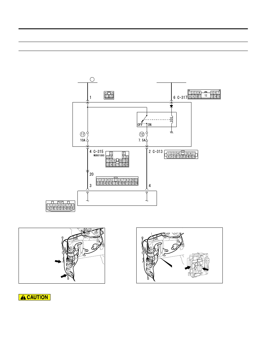
ETACS-ECU

FUSIBLE
LINK

34

IGNITION
SWITCH (IG1)

IG1
RELAY

AWD-ECU

D7G27M002A00

GREY

GREY

GREY

WHITE

WHITE

C-128

C-31

C-309

ZC6000240000

Connectors: C-31, C-128

C-128

C-31

ZC6000260000

ETACS-ECU
(front view)

C-315

C-309
(B)

Connectors: C-309, C-315


If there is any problem in the CAN bus lines, an
incorrect DTC may be set. Prior to this diagnosis,
always diagnose the CAN bus lines.

OPERATION
AWD-ECU detects a power supply voltage abnormal
drop, and if any abnormality occurs, it interrupts the
system.

ELECTRONIC CONTROL AWD

27C-31

DIAGNOSIS

DTC SET CONDITIONS
If the following conditions are met when the system is
activated,  AWD-ECU  gradually  switches  the  control
from AWD to FWD, flashes the AWD/LOCK indicators
alternately, and sets the DTC No. C2100.

IG1 voltage: Less than 8 V

Voltage  between  the  battery  and  ETACS-ECU:
Less than 8 V

Engine speed: more than 1500 r/min

TROUBLESHOOTING HINTS

Current trouble

Damaged wiring harness and connectors

Short  to  earth  or  open  circuit  between  the
battery and AWD-ECU

Past trouble

Intermittent wiring harness or connector failure

NOTE: 

For diagnosis procedures, refer to "How

to treat past trouble". (Refer to GROUP 00, How
to Treat Past Trouble P.00-17.)

DIAGNOSIS

MB991958: Scan Tool (M.U.T.-III Sub Assembly)

MB991824: Vehicle Communication Interface

MB991827: M.U.T.-III USB Cable

MB991910: M.U.T.-III Main Harness A

STEP 1. Battery voltage check
Check the battery voltage.

Q:Is the check result normal?

YES:

 Go to Step 2.

NO:

 Charge or replace the battery.

STEP 2. Voltage measurement at the ETACS-ECU
connector

(1)

Disconnect the C-309 ETACS-ECU connector.

ZC3047220000

C-309 harness 
connector: 
harness side 

(2)

Measure  the  voltage  between  the  C-309  harness  side
connector terminal No. 1 and the body earth.

OK: Battery voltage

Q:Is the check result normal?

YES:

 Go to Step 11.

NO:

 Go to Step 3.

STEP 3. Wiring harness check
Check the wiring harness between the battery and the C-309
ETACS-ECU connector for damage or other problem.

Q:Is the wiring harness in good condition?

YES:

 Go to Step 4.

NO:

 Repair damage or other problem in the wiring harness.

Then go to Step 11.

STEP 4. Scan tool MB991958 CAN bus diagnostics
Use scan tool MB991958 to diagnose the CAN bus lines.

Q:Is the check result normal?

YES:

 Go to Step 6.

27C-32

ELECTRONIC CONTROL AWD

DIAGNOSIS

NO:

 Repair the CAN bus line. (Refer to GROUP 54D - CAN

bus diagnostic chart P.54D-17.) On completion, go to
Step 5.

STEP 5. Check whether the DTC is reset after repairing the
CAN bus line.

(1)

Erase the DTC.

(2)

Turn the ignition switch from the LOCK (OFF) position to the
ON position.

(3)

Start the engine, and continue to run at 1500 r/min or more.

(4)

Check if the DTC is set.

Q:Is the DTC No. C2100 set?

YES:

 Go to Step 6.

NO:

 This diagnosis is complete.

STEP 6. Check the following connector:
Check the connectors below for improper engagement, terminal
damage or terminal drawn in the connector case.

C-128 AWD-ECU connector

C-309, C-315 ETACS-ECU connector

C-31 intermediate connector

Q:Are the connectors and terminals in good condition?

YES:

 Go to Step 7.

NO:

 Repair the connector(s) or terminal(s). Then go to

Step 11.

STEP 7. Wiring harness check
Check  the  wiring  harness  between  the  C-128  AWD-ECU
connector and the C-315 ETACS-ECU connector for damage or
other problem.

Q:Is the wiring harness in good condition?

YES:

 Go to Step 8.

NO:

 Repair damage or other problem in the wiring harness.

Then go to Step 11.

STEP 8. Voltage measurement at the AWD-ECU connector

(1)

Disconnect the C-128 AWD-ECU connector.

C-128 harness 
connector: 
harness side 

ZC3047200000

(2)

Measure the voltage between the C-128 wiring harness side
connector terminals No. 4 and No. 10.

OK: Battery voltage

Q:Is the check result normal?

YES:

 Go to Step 9.

NO:

 Go to Step 11.

STEP 9. Wiring harness check
Check  the  wiring  harness  between  the  C-128  AWD-ECU
connector  (terminal  No.  3)  and  the  C-309  ETACS-ECU
connector (terminal No. 1) for damage or other problem.

Q:Is the wiring harness in good condition?

ELECTRONIC CONTROL AWD

27C-33

DIAGNOSIS

YES:

 Go to Step 10.

NO:

 Repair the wiring harness. Then go to Step 11.

STEP 10. Check whether the DTC is reset.

(1)

Erase the DTC.

(2)

Turn the ignition switch from the LOCK (OFF) position to the
ON position.

(3)

Start the engine, and continue to run at 1500 r/min or more.

(4)

Check if the DTC is set.

Q:Is the DTC No. C2100 set?

YES:

 Replace AWD-ECU. (Refer to P.27C-92.) Then go to

Step 11.

NO:

 The trouble can be an intermittent malfunction.

(Refer to GROUP 00 - How to Cope with Intermittent
Malfunction P.00-15.)

STEP 11. Check whether the DTC is reset.

(1)

Erase the DTC.

(2)

Turn the ignition switch from the LOCK (OFF) position to the
ON position.

(3)

Start the engine, and continue to run at 1500 r/min or more.

(4)

Check if the DTC is set.

Q:Is the DTC No. C2100 set?

YES:

 Diagnose again from Step 1.

NO:

 This diagnosis is complete.

27C-34

ELECTRONIC CONTROL AWD

DIAGNOSIS


Content   ..  566  567  568  569   ..