Mitsubishi Outlander XL. Manual - part 562
 

  Index      Mitsubishi     Mitsubishi Outlander XL - service repair manual 2007 year


Search            


Content   ..  560  561  562  563   ..


Mitsubishi Outlander XL. Manual - part 562


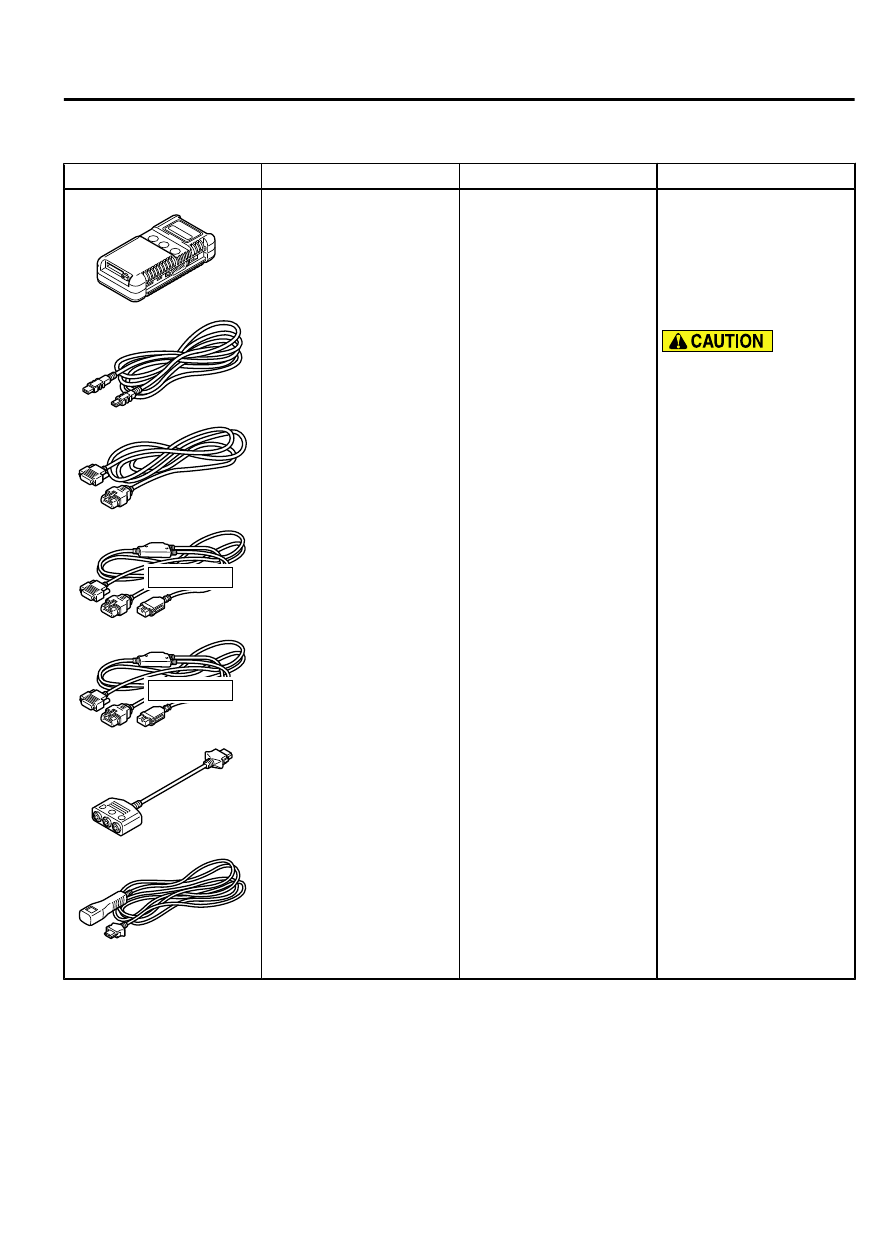
SPECIAL TOOL

M12704100004USA0000010000

Tool

Tool number and name Supersession

Application

MB991910

MB991826

YB9919580000

MB991911

MB991914

MB991824

MB991827

MB991825

Do not use

Do not use

a

b

c

d

e

f

g

MB991958

A: MB991824
B: MB991827
C: MB991910
D: MB991911
E: MB991914
F: MB991825
G: MB991826

M.U.T.-III Sub Assembly

A:

 Vehicle

communication
interface (V.C.I.)
B: M.U.T.-III USB Cable
C:

 M.U.T.-III

 Main

Harness  A  (Vehicles
with

 CAN

communication system)
D:

 M.U.T.-III

 Main

Harness  B  (Vehicles
without

 CAN

communication system)
E:

 M.U.T.-III

 main

harness  C  (for  Daimler
Chrysler models only)
F:  M.U.T.-III  Adapter
Harness
G:  M.U.T.-III  Trigger
Harness

MB991824-KIT

NOTE: 

G: MB991826

M.U.T.-III Trigger
Harness is not necessary
when pushing V.C.I.
ENTER key.

Check  of  the  electronic
control

 AWD

 (the

diagnosis  code  display,
service

 data

 display,

freeze frame data display,
actuator test with M.U.T.-
III)

For  vehicles  with  CAN
communication,

 use

M.U.T.-III  main  harness
A  to  send  simulated
vehicle  speed.  If  you
connect  M.U.T.-III  main
harness  B  instead,  the
CAN

 communication

does

 not

 function

correctly.

ELECTRONIC CONTROL AWD

27C-7

SPECIAL TOOL

Tool

Tool number and name Supersession

Application

YB9912230000

Do not use

a

b

c

d

MB991223
Harness set
A: MB991219
Test harness
B: MB991220
LED harness
C: MB991221
LED harness adapter
D: MB991222
Probe

MB991223

Continuity  check  and
voltage  measurement  at
the  AWD-ECU  wiring
harness connector

MB992006

YB992006AA01

MB992006
Extra fine probe

General service tool

DIAGNOSIS

STANDARD FLOW OF DIAGNOSTIC TROUBLESHOOTING

M12704100006USA0000010000

Refer  to  GROUP  00  -  Troubleshooting  Contents  P.
00-6.

PRECAUTIONS FOR DIAGNOSIS

M12704100007USA0000010000

After troubleshooting, and removing/installing of the
electronic control AWD system components, check
the diagnosis code using M.U.T.-III. If a diagnosis
code  is  set,  erase  it  and  check  again  that  no
diagnosis code is set.

Before performing a troubleshooting, check that all
four  wheels  and  tyres  are  same  in  size.  The
electronic  control  AWD  system  will  function
correctly  only  when  all  four  wheels  and  tyres  are
same in size.

If any abnormality occurs in the electronic control
AWD  system,  it  flashes  the  indicators  (AWD  and
AWD LOCK) in the combination meter alternately to
inform of the abnormality.

When  the  vehicle  is  used  under  some  severe
operational conditions (such as a long-time driving

in AWD on a sandy road, slushy road or road with
deep  snows  or  towing  or  long  hill-climbing),  the
electronic control AWD system illuminates the drive
system  fluid  temperature  warning  lamp  in  the
combination meter in order to protect the electronic
control coupling fluid temperature, at the same time
it  flashes  the  indicator  (AWD  or  LOCK)
corresponding to the selected drive mode to inform
of the abnormality.

The electronic control AWD system is equipped with
the fail-safe function which prohibits AWD control
and shifts to FWD control if any abnormality occurs
in  the  system.  If  there  is  a  risk  that  the  vehicle
behaviour suddenly changes, the gradual shifting to
FWD control is chosen.

27C-8

ELECTRONIC CONTROL AWD

DIAGNOSIS

CHECK OF DRIVE MODE INDICATORS (AWD/

LOCK)

M12704100008USA0000010000

ZC6000190000

Drive mode indicator

Vehicles for USA

ZC6000200000

Drive mode indicator

Vehicles for Canada

Check that the AWD/LOCK indicators illuminate as follows:

1.

Switch the drive mode selector to the LOCK mode.

2.

When  the  ignition  switch  is  turned  ON,  the  AWD/LOCK
indicators illuminate.

3.

After the engine starts, the AWD/LOCK indicators go off.

4.

Otherwise, check the diagnosis code.

DIAGNOSTIC FUNCTION

M12704100009USA0000010000

HOW TO READ DIAGNOSIS CODE

Refer to GROUP 00 - Diagnostic Function .

HOW TO ERASE DIAGNOSIS CODE

Refer to GROUP 00 - Diagnostic Function .

DIAGNOSIS CODE CHART

M12704100010USA0000010000

On troubleshooting, if the ignition switch is turned
ON while disconnecting connector(s), diagnosis
code(s) associated with other system may be set.

On completion, confirm all systems for diagnosis
code(s). If diagnosis code(s) are set, erase them
all.

Diagnosis code No.

Diagnostic item

Reference
page

C1078

Tire with incorrect diameter equipped

 P.27C-10

C1456

Wiring harness or coupling coil overcurrent failure

 P.27C-13

C145A

Wiring harness or coupling coil short circuit failure

 P.27C-17

C145D

Wiring harness or coupling open circuit failure

 P.27C-21

ELECTRONIC CONTROL AWD

27C-9

DIAGNOSIS

Diagnosis code No.

Diagnostic item

Reference
page

C145F

Coupling overload

 P.27C-25

C1460

Drive mode selector circuit failure

 P.27C-27

C2100

Abnormal battery voltage (too low)

 P.27C-31

C2101

Abnormal battery voltage (too high)

 P.27C-35

C211C

Abnormal IG1 power supply low voltage

 P.27C-39

C211D

Abnormal IG1 power supply high voltage

 P.27C-42

C211E

Abnormal power supply voltage (too low)

 P.27C-45

C211F

Abnormal power supply voltage (too high)

 P.27C-48

C2208

AWD-ECU internal error

 P.27C-52

U0001

Bus-off error

 P.27C-56

U0100

Engine CAN time-out

 P.27C-58

U0121

ABS CAN time-out

 P.27C-62

U0141

ETACS CAN time-out

 P.27C-64

U0401

Engine CAN data error

 P.27C-66

U0415

ABS CAN data error

 P.27C-69

U113C

Wheel speed sensor data error

 P.27C-72

DIAGNOSTIC TROUBLE CODE PROCEDURES

DTC C1078: Tire with incorrect diameter equipped

M12704100012USA0000010000

If there is any problem in the CAN bus lines, an incorrect
DTC may be set. Prior to this diagnosis, always diagnose
the CAN bus lines.

OPERATION
If  the  vehicle  is  driven  with  a  tire  with  incorrect
diameter  (high-pressure  type  spare  tire  or  flat  tire)
installed to either wheel in the AWD mode, AWD-ECU
controls the coupling in high torque. If this is the case,
the coupling temperature may rise to cause a seizure.

DTC SET CONDITIONS
If  the  following  conditions  are  met,  AWD-ECU
gradually  reduces  the  AWD  control  torque  to  the
specified  torque,  flashes  the  AWD/LOCK  indicators
alternately, and sets the DTC No. C1078.

AWD selector switch: AWD/LOCK

If the vehicle is driven with abnormal tire pressure
or tires of different brands, DTC No. C1078 is set
and the mode is switched to the AWD AUTO mode.

If the difference in rotation speed between the front
and  rear  wheels  exceeds  a  specific  value
continuously, the DTC No. C1078 is set, the AWD/
LOCK indicators flash alternately, and the mode is
switched to the 2WD mode.

TROUBLESHOOTING HINTS

Current trouble

Tire  with  incorrect  diameter  (high-pressure  type
spare tire or flat tire) equipped

Improper adjusted tire pressure

27C-10

ELECTRONIC CONTROL AWD

DIAGNOSIS


Content   ..  560  561  562  563   ..