Mitsubishi Outlander XL. Manual - part 419
 

  Index      Mitsubishi     Mitsubishi Outlander XL - service repair manual 2007 year


Search            


Content   ..  417  418  419  420   ..


Mitsubishi Outlander XL. Manual - part 419


INJECTOR

Required Special Tools:

MB991658: Test Harness

MB992110: Power Plant ECU Check Harness

Measurement Method

1

2

3

6

7

8

4

5

9 10

ZK603391

Oscilloscope

MB991658

B-21 Intermediate
connector

AA00

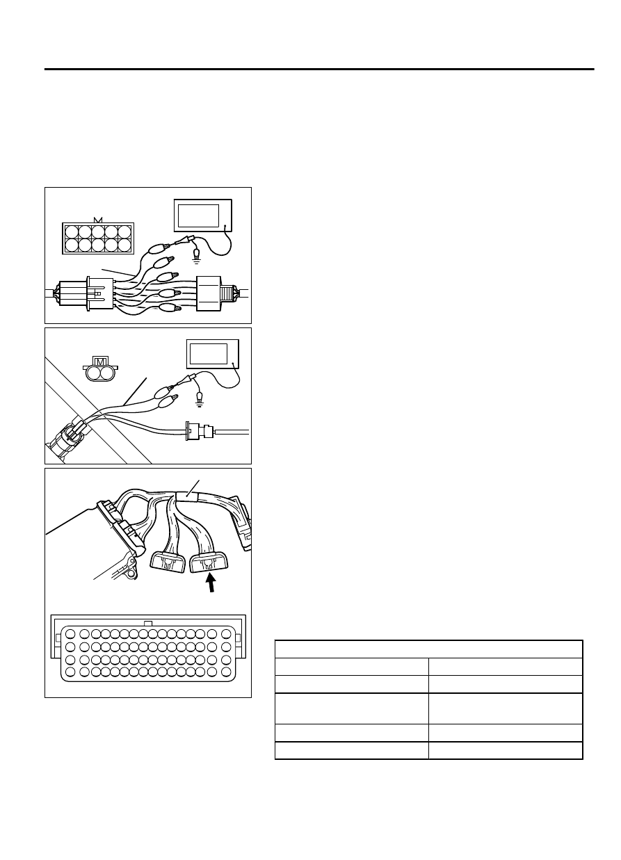
Measure at the right bank (number 1, 3, 5 cylinders)

1.

Disconnect  the  intermediate  connector  B-21,  and  connect
the  test  harness  special  tool  (MB991658)  between  the
separated connector.

2.

Connect  the  oscilloscope  probe  to  each  intermediate
connector B-21 terminal to analyze each cylinder:

Terminal No. 7 for the number 1 cylinder

Terminal No. 8 for the number 3 cylinder

Terminal No. 9 for the number 5 cylinder

ZK603392

1 2

Injector
connector

MB991658

Oscilloscope

AA00

Measure at the right bank (number 2, 4, 6 cylinders)

1.

Disconnect  the  injector  connector,  and  connect  the  test
harness  special  tool  (MB991658)  between  the  separated
connector. (All terminals should be connected.)

2.

Connect the oscilloscope probe to injector connector terminal
No. 2.

16 15 14 13 12 11 10 9 8 7 6 5 4 3

2

1

32 31 30 29 28 27 26 25 24 23 22 21 20 19 18 17

48 47 46 45 44 43 42 41 40 39 38 37 36 35 34 33

64 63 62 61 60 59 58 57 56 55 54 53 52 51 50 49

ZK603390 AA00

Power Plant ECU
Check Harness Connector

MB992110

Alternate method

1.

Disconnect all ECM connectors. Connect the check harness
special tool (MB992110) between the separated connectors.

2.

Connect  the  oscilloscope  probe  to  each  check  harness
connector terminal to analyze each cylinder:

Terminal No. 2 for the number 1 cylinder.

Terminal No. 3 for the number 2 cylinder.

Terminal No. 18 for the number 3 cylinder.

Terminal No. 19 for the number 4 cylinder.

Terminal No. 50 for the number 5 cylinder.

Terminal No. 51 for the number 6 cylinder.

Standard Wave Pattern

Observation conditions
Function

Special pattern

Pattern height

Variable

Variable knob

Adjust  while  viewing  the
wave pattern

Pattern selector

Display

Engine r/min

Idle speed

MULTIPORT INJECTION SYSTEM (MFI) <DIAGNOSIS>

13Ab-871

INSPECTION PROCEDURE USING AN OSCILLOSCOPE

ZK603395

(V)

50

0

Drive signal:"ON"

Point A

Point B:
Injector drive time

Drive signal:"OFF"

Power voltage

Injection coil induced
voltage (Approximately 50-60V)

AA00

Standard wave pattern

Wave Pattern Observation Points

Point A: Height of injector coil induced voltage.

CONTRAST

 WITH

STANDARD

 WAVE

PATTERN

PROBABLE CAUSE

Injector coil induced voltage is
low or doesn't appear at all

Short in the injector solenoid

Point B: Injector drive time

ZK601084

WHEN IDLING

WHEN RACING

AA00

1.

The injector drive time should be synchronized with the scan
tool tester display.

2.

When the engine is suddenly revved, the drive time will be
greatly extended at first, but the drive time will soon return to
original length.

EGR VALVE (STEPPER MOTOR)

Required Special Tools:

MB991658: Test Harness

MB992110: Power Plant ECU Check Harness

13Ab-872

MULTIPORT INJECTION SYSTEM (MFI) <DIAGNOSIS>

INSPECTION PROCEDURE USING AN OSCILLOSCOPE

Measurement Method

ZK603620

1

2 3

4

5 6

EGR VALVE
CONNECTOR

OSCILLOSCOPE

MB991658

AA00

1.

Disconnect  the  EGR  valve  connector,  and  connect  the  test
harness  special  tool  (MB991658)  between  the  separated
connector (All terminals should be connected).

2.

Connect the oscilloscope probe to the EGR valve connector
terminal No. 1, terminal No. 3, terminal No. 4, terminal No. 6
respectively.


Alternate method

16 15 14 13 12 11 10 9 8 7 6 5 4 3

2

1

32 31 30 29 28 27 26 25 24 23 22 21 20 19 18 17

48 47 46 45 44 43 42 41 40 39 38 37 36 35 34 33

64 63 62 61 60 59 58 57 56 55 54 53 52 51 50 49

ZK603390 AA00

Power Plant ECU
Check Harness Connector

MB992110

1.

Disconnect all ECM connectors. Connect the check harness
special tool (MB992110 between the separated connectors.

ZK603621

16

15 14 13 12 11 10 9 8 7 6 5 4 3

2

1

32

31 30 29 28 27 26 25 24 23 22 21 20 19 18 17

48 47 46 45 44 43 42 41 40 39 38 37 36 35 34 33

64

63 62 61 60 59 58 57 56 55 54 53 52 51 50 49

AA00

OSCILLOSCOPE

POWER PLANT ECU
CHECK HARNESS
CONNECTOR

2.

Connect the oscilloscope probe to check harness terminal No.
31, No. 32, No. 47 and No. 48.

Standard Wave Pattern

Observation condition
Function

Special pattern

Pattern height

High

Pattern selector

Display

Engine condition

Revving


MULTIPORT INJECTION SYSTEM (MFI) <DIAGNOSIS>

13Ab-873

INSPECTION PROCEDURE USING AN OSCILLOSCOPE

ZK603396 AA00

(V)

30

20

10

0

EGR valve
(stepper moter)
control signal
wave pattern

Point B coil reverse
electromotive force
(approximatery 3 ×10V) Point an induced

electromotive force
from the moter turning

Time

Standard wave pattern

The wave patern
appears for an
instant, but soon
disappears.

Wave Pattern Observation Points

1.

Check that the standard wave pattern appears when the EGR
valve is operating.

Point A: Presence or absence of induced electromotive force
from the motor turning. (Refer to abnormal wave pattern.)

CONTRAST

 WITH

STANDARD

 WAVE

PATTERN

PROBABLE CAUSE

Induced  electromotive  force
does  not  appear  or  is
extremely small

Malfunction of motor

Point B: Height of coil back electromotive force

CONTRAST

 WITH

STANDARD

 WAVE

PATTERN

PROBABLE CAUSE

Coil  reverse  electromotive
force  does  not  appear  or  is
extremely small

Short in the coil

13Ab-874

MULTIPORT INJECTION SYSTEM (MFI) <DIAGNOSIS>

INSPECTION PROCEDURE USING AN OSCILLOSCOPE


Content   ..  417  418  419  420   ..