Mitsubishi Outlander XL. Manual - part 335
 

  Index      Mitsubishi     Mitsubishi Outlander XL - service repair manual 2007 year


Search            


Content   ..  333  334  335  336   ..


Mitsubishi Outlander XL. Manual - part 335


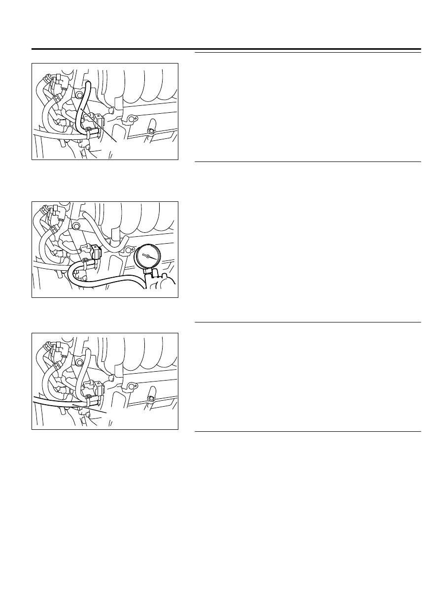
STEP 2. Check for leaks in evaporative emission hose A.

ZK603398AA00

Hose A


Use a hand vacuum pump to check the hose A.

Q:Do the hose hold vacuum?

YES:

 Go to Step 3.

NO:

 Replace the hose. Then go to Step 14.

STEP 3. Check the evaporative emission purge solenoid for
leaks.

(1)

Disconnect the hose A from the evaporative emission purge
solenoid.

ZK603399AA00

(2)

Connect the hose of the hand vacuum pump to the intake
manifold  side  nipple  of  the  evaporative  emission  purge
solenoid.

(3)

Use the hand vacuum pump to confirm that the evaporative
emission purge solenoid holds vacuum.

(4)

Connect  the  hose  A  to  the  evaporative  emission  purge
solenoid.

Q:Does  the  evaporative  emission  purge  solenoid  hold

vacuum?

YES:

 Go to Step 4.

NO:

 Replace the evaporative emission purge solenoid.

Then go to Step 14.

STEP 4. Check for leaks in evaporative emission B.

ZK603400AA000

Hose B


Use a hand vacuum pump to check the hose B.

Q:Do the hose hold vacuum?

YES:

 Go to Step 5.

NO:

 Replace any damaged hose. Then go to Step 14.

STEP 5. Using scan tool MB991958, check actuator test item
15: Evaporative emission ventilation solenoid.

(1)

Remove the canister cover.

(2)

Remove  the  evaporative  emission  ventilation  solenoid.  Do
not disconnect the connector.

MULTIPORT INJECTION SYSTEM (MFI) <DIAGNOSIS>

13Ab-535

DIAGNOSTIC TROUBLE CODE PROCEDURES

ZK603401AA00

Evaporative emission
ventilation solenoid

Evaporative emission
ventilation solenoid

Intake manifold
side nipple

(3)

Connect the hose of the hand vacuum pump to the canister
side nipple of the evaporative emission ventilation solenoid.

(4)

Turn the ignition switch to the "ON" position.

(5)

Set scan tool MB991958 to actuator test mode.

Item 15: Evaporative Emission Ventilation Solenoid.

While the evaporative emission ventilation solenoid is
energized,  operate  the  hand  vacuum  pump  and
confirm that the solenoid holds vacuum.

(6)

Turn the ignition switch to the "LOCK" (OFF) position.

(7)

Disconnect  the  hand  vacuum  pump,  and  reinstall  the
evaporative emission ventilation solenoid.

(8)

Reinstall the canister cover.

Q:Did  the  evaporative  emission  ventilation  solenoid  hold

vacuum?

YES:

 Go to Step 6.

NO:

 Replace the evaporative emission ventilation

solenoid (Refer to GROUP 17, Evaporative emission
canister and fuel tank pressure relief valve removal and
installation P.17c-18).Then go to Step 14.

STEP 6. Pressure test the evaporative emission system
lines from hoses C to I.

ZK603404

Hose C

AA00

(1)

Disconnect  hose  C  from  the  canister  while  holding  the
release  buttons  indicated  in  the  illustration  pressed  by
fingers.

ZK603402

Hose C

Plug

AA00

(2)

Plug the disconnected end of hose C.

(3)

Confirm  that  the  evaporative  emission  system  pressure
pump (Miller number 6872A) is operating properly. Perform
the  self-test  as  described  in  the  pump  manufacturer's
instructions.

(4)

Remove the fuel cap.

13Ab-536

MULTIPORT INJECTION SYSTEM (MFI) <DIAGNOSIS>

DIAGNOSTIC TROUBLE CODE PROCEDURES

ZK603403AA00

(5)

Connect  the  evaporative  emission  system  pressure  pump
(Miller number 6872A) to the fuel tank filler tube by using fuel
tank adapter (MLR-8382).

(6)

Pressure test the system to determine whether any leaks are
present.

NOTE: 

The "Pressure test" in this procedure refers to

the I/M240 Simulation Test. The eight steps of this test
are described in the manufacturer's instructions for the
evaporative emission system pressure pump, Miller number
6872A.

(7)

Remove  the  evaporative  emission  system  pressure  pump
(Miller number 6872A) and the fuel tank adapter (MLR-8382),
and reinstall the fuel cap.

(8)

Connect hose C to the evaporative emission canister.

Q:Is the evaporative emission system line free of leaks?

YES:

 Go to Step 12.

NO:

 Go to Step 7.

STEP 7. Check for leaks in evaporative emission hoses C
through F.

ZK603405

Hose C

AA00

ZK603406

Hose E

Hose F

AA00

Hose D


Use a hand vacuum pump to test each hose from hose C to
hose F.

Q:Do the hoses hold vacuum?

YES:

 Go to Step 8.

NO:

 Replace any damaged hose. Then go to Step 14.

MULTIPORT INJECTION SYSTEM (MFI) <DIAGNOSIS>

13Ab-537

DIAGNOSTIC TROUBLE CODE PROCEDURES

STEP 8. Test check valve.

ZK603407

Check valve

AA00

(1)

Check valve is a one-way check valve.

ZK603408AA00

Check valve

(2)

Check valve should allow air to flow in only one direction.

Q:Does check valve allow air to pass in one direction only?

YES:

 Go to Step 9.

NO:

 Replace check valve, and reinstall the fuel tank

filler tube protector (Refer to GROUP 13B, Fuel Tank
<FWD> P.13B-13or Fuel Tank <AWD> P.13B-18). Then go
to Step 14.

STEP 9. Check for leaks in evaporative emission hoses G
and H.

ZK603409

Hose G

Hose H

AA00


Use a hand vacuum pump to test each hose G and H.

Q:Do the hoses hold vacuum?

YES:

 Go to Step 10.

NO:

 Replace any damaged hose. Then go to Step 14.

STEP 10. Check for leaks in evaporative emission hose I.

(1)

Remove the fuel tank assembly (Refer to GROUP 13B, Fuel
Tank  <FWD>  P.13B-13or  Fuel  Tank  <AWD>  P.
13B-18).

ZK603410

Hose I

AA00

(2)

Use the hand vacuum pump to check the hose I.

Q:Do the hose hold vacuum?

YES:

 Go to Step 11.

NO:

 Replace the hose and reinstall the fuel tank assembly

(Refer to GROUP 13B, Fuel Tank <FWD> P.13B-13or Fuel
Tank <AWD> P.13B-18). Then go to Step 14.

13Ab-538

MULTIPORT INJECTION SYSTEM (MFI) <DIAGNOSIS>

DIAGNOSTIC TROUBLE CODE PROCEDURES


Content   ..  333  334  335  336   ..