Mitsubishi Outlander XL. Manual - part 260
 

  Index      Mitsubishi     Mitsubishi Outlander XL - service repair manual 2007 year


Search            


Content   ..  258  259  260  261   ..


Mitsubishi Outlander XL. Manual - part 260


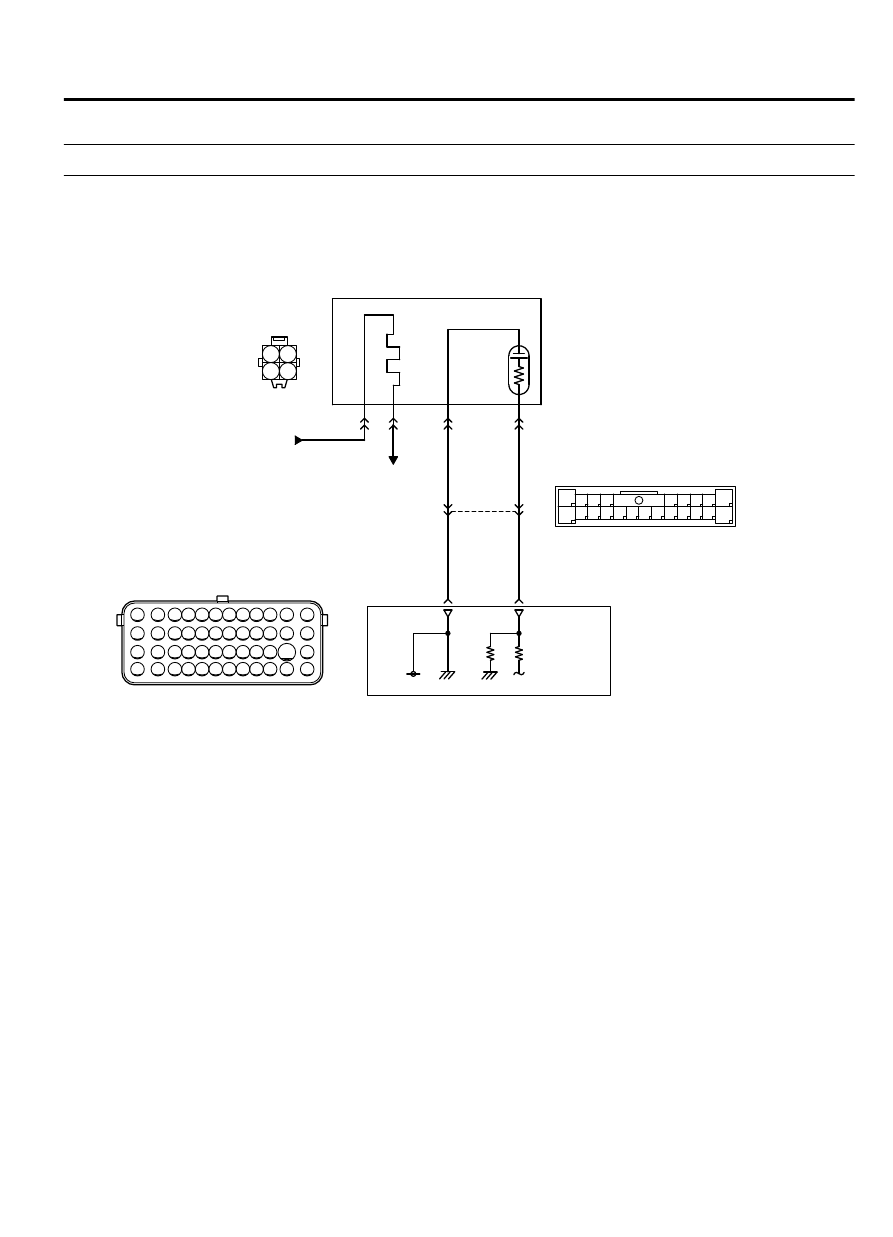
DTC P0143: Heated Oxygen Sensor Circuit Low Voltage (bank 1, sensor 3) <California>

M11310100363USA0000010000

ZK602864

1 2
3 4

71 72 73 74 75 76 77 78 79 80 81 82

83 84 85 86 87 88 89 90 91 92 93 94

95 96 97 98 99

100 101 102 103 104

112 113 114

109

108

107

110 111

115 116

106

105

118

117

2

8

7

6

5

4

3

11

21

20

19

18

17

16

15

14

13

12

9

22

1

10

AA00

D-30

FROM MFI RELAY

TO ECM

1

4

2

3

CENTER EXHAUST PIPE HEATED OXYGEN SENSOR CIRCUIT

CENTER EXHAUST PIPE
HEATED OXYGEN
SENSOR

B-11

YELLO

W

ORANGE

ORANGE

YELLO

W

ENGINE
CONTROL
MODULE

0.5 V

C-129

15

116

101

17

MULTIPORT INJECTION SYSTEM (MFI) <DIAGNOSIS>

13Ab-235

DIAGNOSTIC TROUBLE CODE PROCEDURES

ZK600417 AA00

Center exhaust pipe
heated oxygen sensor

Connector: D-30

D-30 (B)

Rear heater duct

ZK603592

ECM

B-11 (GR)

Connector: B-11

AA00

ZK603651AA00

C-129

Connector: C-129


CIRCUIT OPERATION

A  voltage  corresponding  to  the  oxygen
concentration in the exhaust gas is sent to the ECM
(terminal No. 101) from the output terminal (terminal
No. 3) of the Center exhaust pipe heated oxygen
sensor.

Terminal No. 4 of the Center exhaust pipe heated
oxygen sensor is grounded with ECM (terminal No.
116).

The ECM applies an off set voltage of 0.5 volt to
terminal No. 4 of the Center exhaust pipe heated
oxygen sensor.

DECHNICAL DESCRIPTION
The  ECM  checks  for  the  right  bank  heated  oxygen
sensor (rear) output voltage.

DESCRIPTIONS OF MONITOR METHODS

Center exhaust pipe heated oxygen sensor output
voltage is under the specified range.

MONITOR EXECUTION

Continuous

MONITOR EXECUTION CONDITIONS (Other
monitor and Sensor)

Other Monitor (There is no temporary DTC stored in
memory for the item monitored below)

Center exhaust pipe heated oxygen sensor heater
(front) monitor

Sensor (The sensor below is determined to be
normal)

Engine coolant temperature sensor

13Ab-236

MULTIPORT INJECTION SYSTEM (MFI) <DIAGNOSIS>

DIAGNOSTIC TROUBLE CODE PROCEDURES

DTC SET CONDITIONS

Logic Flow Chart

End

Malfunction

Yes

Yes

Yes

No

No

No

2secs have passed?

Output voltage

< 0.2V

Monitoring

conditions

Good

Start

ZK603708 AA00

Check Conditions

Heated oxygen sensor offset voltage is between 0.4
and 0.6 volt.

Battery  positive  voltage  is  between  11  and  16.5
volts.

3 minutes or more have passed since the engine
starting sequence was completed.

Judgement Criterion

Center exhaust pipe heated oxygen sensor output
voltage is lower than 0.2 volt for 2 seconds.

OBD-II DRIVE CYCLE PATTERN

Refer to Diagnostic Function - OBD-II Drive Cycle -
Pattern 23 P.13Ab-8.

TROUBLESHOOTING HINTS (The most likely
causes for this code to be set are:)

Center exhaust pipe Heated oxygen sensor failed.

Connector damage.

Harness damage

ECM failed.


MULTIPORT INJECTION SYSTEM (MFI) <DIAGNOSIS>

13Ab-237

DIAGNOSTIC TROUBLE CODE PROCEDURES

DIAGNOSIS

Required Special Tools:

MB991958: Scan Tool (M.U.T.-III Sub Assembly)

MB991824: V.C.I.

MB991827: USB Cable

MB991910: Main Harness A

MB991658: Test Harness

STEP 1. Check harness connector D-30 at the center
exhaust pipe heated oxygen sensor and harness connector
B-11 at the ECM for damage.

Q:Is the harness connector in good condition?

YES:

 Go to Step 2.

NO:

 Repair it. Refer to GROUP 00E, Harness Connector

Inspection P.00E-2. Then go to Step 4.

STEP 2. Check the center exhaust pipe heated oxygen
sensor (rear).

(1)

Disconnect the center exhaust pipe heated oxygen sensor
connector  D-30  and  connect  test  harness  special  tool,
MB991658, to the connector on the right bank heated oxygen
sensor side.

(2)

Warm  up  the  engine  until  engine  coolant  temperature
reaches 80°C (176°F) or higher.

(3)

Drive at 50 km/h (31 mph) or more for 10 minutes.

ZK600444

MB991658

AA00

Heated oxygen
sensor component
side connector

(4)

Connect a digital voltage meter between terminal No. 3 and
terminal No. 4.

(5)

Measure the output voltage of heated oxygen sensor under
the following driving.

a
.

Transaxle: 2nd speed

b
.

Drive with wide open throttle

c
.

Engine: 3,500 r/min or more

Standard value: 0.6 - 1.0 volts

NOTE: 

If the sufficiently high temperature [of

approximate 400°C (752°F) or more] is not reached
although the heated oxygen sensor is normal, the output
voltage would be possibly low although the rich air/fuel
ratio.

Q:Is the voltage between 0.6 and 1.0 volts?

YES:

 Go to Step 3.

NO:

 Replace the center exhaust pipe heated oxygen sensor.

Then go to Step 4.

13Ab-238

MULTIPORT INJECTION SYSTEM (MFI) <DIAGNOSIS>

DIAGNOSTIC TROUBLE CODE PROCEDURES


Content   ..  258  259  260  261   ..