Mitsubishi Outlander XL. Manual - part 257
 

  Index      Mitsubishi     Mitsubishi Outlander XL - service repair manual 2007 year


Search            


Content   ..  255  256  257  258   ..


Mitsubishi Outlander XL. Manual - part 257


ZK603593AA00

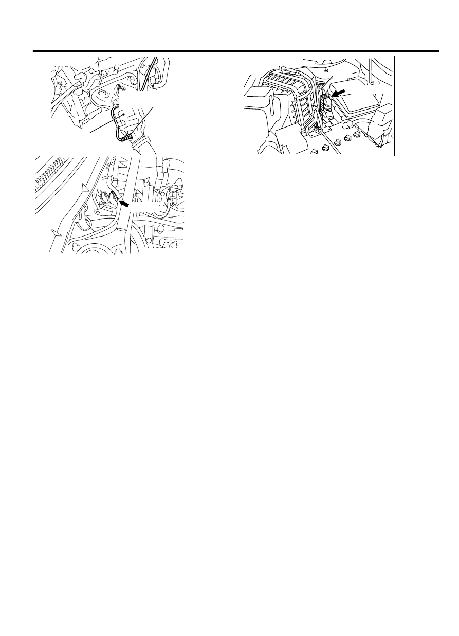
Right bank heated
oxygen sensor (rear)

Front exhaust 
pipe RH

B-02 (B)

Connector: B-02

ZK603591

ECM

B-10 (GR)

Connector: B-10

AA00


CIRCUIT OPERATION

A  voltage  corresponding  to  the  oxygen
concentration in the exhaust gas is sent to the ECM
(terminal No. 56) from the output terminal (terminal
No.  4)  of  the  right  bank  heated  oxygen  sensor
(rear).

Terminal  No.  2  of  the  right  bank  heated  oxygen
sensor (rear) is grounded with ECM (terminal No.
57).

The  ECM  applies  an  offset  voltage  of  0.5  volt  to
terminal  No.  2  of  the  right  bank  heated  oxygen
sensor (rear).

TECHNICAL DESCRIPTION

The output signal of the right bank heated oxygen
sensor (front) is compensated by the output signal
of the right bank heated oxygen sensor (rear).

The ECM checks for the right bank heated oxygen
sensor (rear) output voltage.

DESCRIPTIONS OF MONITOR METHODS

Right  bank  heated  oxygen  sensor  (rear)  output
voltage is over the specified range.

MONITOR EXECUTION

Continuous

MONITOR EXECUTION CONDITIONS (Other
monitor and Sensor)

Other Monitor (There is no temporary DTC stored in
memory for the item monitored below)

Not applicable

Sensor (The sensor below is determined to be
normal)

Engine coolant temperature sensor

DESCRIPTIONS OF MONITOR METHODS

Right  bank  heated  oxygen  sensor  (rear)  output
voltage is over the specified range.

MONITOR EXECUTION

Continuous

MONITOR EXECUTION CONDITIONS (Other
monitor and Sensor)

Other Monitor (There is no temporary DTC stored in
memory for the item monitored below)

Heated oxygen sensor heater (front) monitor

Heated oxygen sensor heater (rear) monitor

Air/fuel ratio feedback monitor

Sensor (The sensor below is determined to be
normal)

Mass airflow sensor

Engine coolant temperature sensor

MULTIPORT INJECTION SYSTEM (MFI) <DIAGNOSIS>

13Ab-223

DIAGNOSTIC TROUBLE CODE PROCEDURES

Intake air temperature sensor

Barometric pressure sensor

DTC SET CONDITION

Logic Flow Chart

Start

End

No

Yes

Yes

Yes

No

No

Malfunction

Good

Continuous

failure for 2secs

Output voltage

> 1.8V

Monitoring

conditions

ZK603713 AA00

Check Conditions

2 seconds or more have passed since the engine
starting sequence was completed.

Heated  oxygen  sensor  off  set  voltage  is  between
0.4 and 0.6 volt.

Judgement Criterion

Right  bank  heated  oxygen  sensor  (rear)  output
voltage has continued to be 1.8 volts or higher for 2
seconds.

OBD-II DRIVE CYCLE PATTERN

Refer to Diagnostic Function - OBD-II Drive Cycle -
Pattern 24 P.13Ab-8.

TROUBLESHOOTING HINTS (The most likely
causes for this code to be set are: )

Connector damage.

Harness damage

ECM failed.


DIAGNOSIS

Required Special Tools:

MB991958: Scan tool (M.U.T.-III Sub Assembly)

13Ab-224

MULTIPORT INJECTION SYSTEM (MFI) <DIAGNOSIS>

DIAGNOSTIC TROUBLE CODE PROCEDURES

MB991824: V.C.I.

MB991827: USB Cable

MB991910: Main Harness A

STEP 1. Check harness connector B-02 at the right bank
heated oxygen sensor (rear) and harness connector B-10 at
ECM for damage.

Q:Is the harness connector in good condition?

YES:

 Go to Step 2.

NO:

 Repair it. Refer to GROUP 00E, Harness Connector

Inspection P.00E-2. Then go to Step 4.

STEP 2. Check for short circuit to power supply between the
right bank heated oxygen sensor (rear) connector B-02
(terminal No. 4) and the ECM connector B-10 (terminal No.
56).

Q:Is the harness wire in good condition?

YES:

 Go to Step 3.

NO:

 Repair it. Then go to Step 4.

STEP 3. Check the trouble symptoms.

(1)

Carry out a test drive with the drive cycle pattern. Refer to
Diagnostic  Function  -  OBD-II  Drive  Cycle  -  Pattern  24  P.
13Ab-8.

(2)

Check the diagnostic trouble code (DTC).

Q:Is DTC P0138 set?

YES:

 Replace the ECM. When the ECM is replaced, register

the ID code. Refer to GROUP 42B, ID Code Registration
Judgment Table <Vehicles with KOS> P.42B-12or GROUP
42C, ID Code Registration Judgment Table <Vehicles with
WCM> P.42C-8. Then go to Step 4.

NO:

 It can be assumed that this malfunction is

intermittent. Refer to GROUP 00, How to Use
Troubleshooting/Inspection Service Points - How to Cope
with Intermittent Malfunctions P.00-15.

STEP 4. Test the OBD-II drive cycle.

(1)

Carry out a test drive with the drive cycle pattern. Refer to
Diagnostic  Function  -  OBD-II  Drive  Cycle  -  Pattern  24  P.
13Ab-8.

(2)

Check the diagnostic trouble code (DTC).

Q:Is DTC P0138 set?

YES:

 Retry the troubleshooting.

NO:

 The inspection is complete.

MULTIPORT INJECTION SYSTEM (MFI) <DIAGNOSIS>

13Ab-225

DIAGNOSTIC TROUBLE CODE PROCEDURES

DTC P0139: Heated Oxygen Sensor Circuit Slow Response (bank 1, sensor 2)

M11310100192USA0000010000

ZK602839

1

2

3 4 5 6 7 8 9 10 11 12 13 14 15 16

17 18 19 20 21 22 23 24 25 26 27 28 29 30 31 32

33 34 35 36 37 38 39 40 41 42 43 44 45 46 47 48

49 50 51 52 53 54 55 56 57 58 59 60 61 62 63 64

0.5 V

2

1

4

3

AA00

ENGINE
CONTROL
MODULE

RIGHT BANK HEATED
OXYGEN SENSOR (REAR)

FROM MFI RELAY

TO ECM

1

2

3

4

57

PINK

LIGHT GREEN

56

RIGHT BANK HEATED OXYGEN SENSOR (REAR) CIRCUIT

B-10

B-02

MU802605

13Ab-226

MULTIPORT INJECTION SYSTEM (MFI) <DIAGNOSIS>

DIAGNOSTIC TROUBLE CODE PROCEDURES


Content   ..  255  256  257  258   ..