Content .. 1193 1194 1195 1196 ..
Mitsubishi Outlander XL. Manual - part 1195
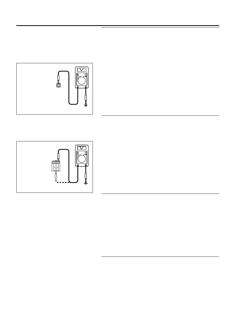
STEP 8. Measure the voltage at A/C compressor assembly
connector B-17.
(1)
Disconnect A/C compressor assembly connector B-17 and
measure the voltage at the wiring harness side.
(2)
Disconnect powertrain control module connector B-11 and
ground harness side terminal No.102.
(3)
Turn the ignition switch to the "ON" position.
ZC602223 0010
Harness side: B-17
(4)
A/C compressor assembly connector B-17 terminal 1 and
ground.
⦆
The measured value should be approximately 12 volts
(battery positive voltage).
Q:Is the measured voltage approximately 12 volts?
YES:
Go to Step 13.
NO:
Go to Step 9.
STEP 9. Measure the voltage at A/C compressor clutch relay
connector B-16X.
(1)
Disconnect A/C compressor connector B-16X and measure
the voltage at the relay box side.
(2)
Turn the ignition switch to the "ON" position.
ZC602223 0011
Harness side: B-16X
(3)
Measure the voltage between terminal 4 and ground.
⦆
The measured value should be approximately 12 volts
(battery positive voltage).
(4)
Measure the voltage between terminal 2 and ground.
⦆
The measured value should be approximately 12 volts
(battery positive voltage).
Q:Is the measured voltage approximately 12 volts?
YES:
Go to Step 11.
NO:
Go to Step 10.
STEP 10. Check the wiring harness between A/C
compressor clutch relay connector B-16X (terminals 2 and
4) and the fusible link (36).
Q:Is the wiring harness between A/C compressor clutch
relay connector B-16X (terminals 2 and 4) and the fusible
link (36) in good condition?
YES:
It can be assumed that this malfunction is
intermittent. Refer to GROUP 00, How to Use
Troubleshooting/Inspection Service Points - How to Cope
with Intermittent Malfunctions P.00-15.
NO:
Repair the wiring harness. Check that the A/C works
normally.
STEP 11. Check the wiring harness between A/C
compressor clutch relay connector B-16X (terminal 3) and
A/C compressor assembly connector B-17 (terminal 1).
NOTE:
Also check intermediate connector A-13 for loose,
corroded, or damaged terminals, or terminals pushed back in
the connector. If intermediate connector A-13 is damaged,
AIR CONDITIONING
55A-71
MANUAL A/C DIAGNOSIS