Mitsubishi Outlander XL. Manual - part 1110


  Index      Mitsubishi     Mitsubishi Outlander XL - service repair manual 2007 year


Search            


Content   ..  1108  1109  1110  1111   ..


Mitsubishi Outlander XL. Manual - part 1110


STEP 3. Check the wiring harness between CAN box unit
connector C-13 (terminal 1) and the ground.

Q:Is the wiring harness between CAN box unit connector

C-13 (terminal 1) and the ground in good condition?

YES:

 No action is necessary and testing is complete.

NO:

 The wiring harness may be damaged or the connector

(s) may have loose, corroded or damaged terminals, or
terminals pushed back in the connector. Repair the wiring
harness as necessary.

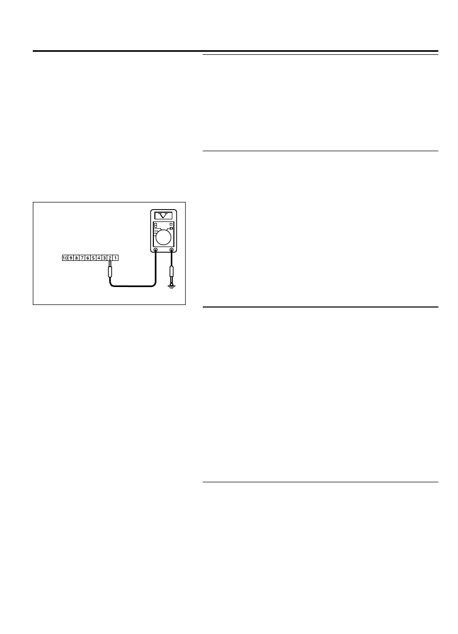
STEP 4. Check the battery power supply circuit to the CAN
box unit. Measure the voltage at CAN box unit connectors
C-13.

(1)

Disconnect  CAN  box  unit  connectors  C-13  measure  the
voltage available at the wiring harness side of the connector.

ZC6022230007

Connector C-13  
(Harness side)

(2)

Measure the voltage between CAN box unit connector C-13
terminal 2 and ground.

The  voltage  should  measure  approximately  12  volts
(battery positive voltage).

Q:Is the measured voltage approximately 12 volts (battery

positive voltage)?

YES:

 Go to Step 6.

NO:

 Go to Step 5.

STEP 5. Check the wiring harness between CAN box unit
connector C-13 (terminal 2) and fusible link (36).

NOTE: 

Also check intermediate connector C-17 and ETACS-ECU

connectors C-307 and C-317 for loose, corroded, or damaged
terminals, or terminals pushed back in the connector. If
intermediate connector C-17 or ETACS-ECU connector C-307 or
C-317 is damaged, repair or replace the connector as
described in GROUP 00E, Harness Connector Inspection P.
00E-2.

Q:Is the wiring harness between CAN box unit connector

C-13 (terminal 2) and fusible link (36) in good condition?

YES:

 No action is necessary and testing is complete.

NO:

 The wiring harness may be damaged or the connector

(s) may have loose, corroded or damaged terminals, or
terminals pushed back in the connector. Repair the wiring
harness as necessary. The system should communicate with
the CAN box unit normally.

STEP 6. Check the wiring harness between CAN box unit
connector C-13 (terminal 10) and fusible link (37).

NOTE: 

Also check intermediate connector C-17 and ETACS-ECU

connectors C-309 and C-315 for loose, corroded, or damaged
terminals, or terminals pushed back in the connector. If
intermediate connector C-17 or ETACS-ECU connectors C-309
or C-315 is damaged, repair or replace the connector as
described in GROUP 00E, Harness Connector Inspection P.
00E-2.

AUDIO AND NAVIGATION SYSTEM

54B-121

DIAGNOSIS

Q:Is the wiring harness between CAN box unit connector

C-13 (terminal 10) and fusible link (37) in good condition?

YES:

 No action is necessary and testing is complete.

NO:

 The wiring harness may be damaged or the connector

(s) may have loose, corroded or damaged terminals, or
terminals pushed back in the connector. Repair the wiring
harness as necessary. The system should communicate with
the CAN box unit normally.

INSPECTION PROCEDURE 12: Communication with scan tool is not possible.

M15410800389USA0000010000

CAN Box Unit Communication Circuit

AUDIO VISUAL 
NAVIGATION UNIT

CAN BOX UNIT

ZC6008760029

Connectors: C-07, C-13

C-07

C-13

COMMENTS ON TROUBLE SYMPTOM
When scan tool MB991958 cannot communicate with
the MMCS (audio visual navigation unit), the CAN bus

line, CAN box unit power supply circuit system, audio
visual  navigation  unit  or,  or  CAN  box  unit  may  be
faulty.

PROBABLE CAUSES

Damaged wiring harness and connectors

Audio visual navigation unit malfunction

CAN box unit malfunction

Wrong routing of scan tool harness

Abnormality  in  power  supply  voltage  to  CAN  box
unit

ECU malfunction of other system

DIAGNOSIS

Required Special Tools:

MB991958: Scan Tool (M.U.T.-III Sub Assembly)

MB991824: Vehicle Communication Interface (V.C.I.)

MB991827: M.U.T.-III USB Cable

54B-122

AUDIO AND NAVIGATION SYSTEM

DIAGNOSIS

MB991910:  M.U.T.-III  Main  Harness  A  (Vehicles  with
CAN communication system)

STEP 1. Perform "Network/Connect Line Check" of the
MMCS service mode.
Perform "Network/Connect Line Check" of the MMCS service
mode, and check that the communication between the CAN box
unit and the audio visual navigation unit is normal. (Refer to P.
54B-64.)

NOTE: 

When the communication between the CAN box unit and

the audio visual navigation unit is normal, "CAN BOX" is
displayed on the check result screen. However, if the
communication is not possible, "CAN BOX" is not displayed.

Q:Is "CAN BOX" displayed?

YES:

 Go to Step 2.

NO:

 Go to Step 3.

STEP 2. Using scan tool MB991958, diagnose the CAN bus
line.

ZC501967

AC404789

ZC5019680000

MB991824

MB991827

MB991910

Data link

connector

To prevent damage to scan tool MB991958, always turn the
ignition  switch  to  the  "LOCK"  (OFF)  position  before
connecting or disconnecting scan tool MB991958.

(1)

Connect  scan  tool  MB991958.  Refer  to  GROUP  54Ad,
ETACS, Diagnosis, "How to connect the Scan Tool (M.U.T.-
III) P.54Ad-5."

(2)

Turn the ignition switch to the "ON" position.

(3)

Diagnose the CAN bus line.

(4)

Turn the ignition switch to the "LOCK" (OFF) position.

Q:Is the CAN bus line found to be normal?

YES:

 Intermittent malfunction is suspected. Refer to

GROUP 00, How to Use Troubleshooting/Inspection Service
Points - How to Cope with Intermittent Malfunction P.
00-15.

NO:

 Repair the CAN bus line. (Refer to GROUP 54D,

Diagnosis P.54D-17).

STEP 3. Check CAN box unit connector C-13 and audio
visual navigation unit connector C-07 for loose, corroded or
damaged terminals, or terminals pushed back in the
connector.

Q:Are  CAN  box  unit  connector  C-13  and  audio  visual

navigation unit connector C-07 in good condition?

YES:

 Go to Step 4.

NO:

 Repair or replace the damaged component(s). Refer to

GROUP 00E, Harness Connector Inspection P.00E-2. The
steering remote control switch should work normally.

AUDIO AND NAVIGATION SYSTEM

54B-123

DIAGNOSIS

STEP 4. Check the wiring harness between CAN box unit
connector C-13 (terminal 4, 5, 6) and audio visual navigation
unit connector C-07 (terminal 43, 59, 58).

Q:Is the wiring harness between CAN box unit connector

C-13  (terminal  4,  5,  6)  and  audio  visual  navigation  unit

connector C-07 (terminal 43, 59, 58) in good condition?

YES:

 Go to Step 5.

NO:

 The wiring harness may be damaged or the connector

(s) may have loose, corroded or damaged terminals, or
terminals pushed back in the connector. Repair the wiring
harness as necessary.

STEP 5. Substitute a known good CAN box unit, and check
the trouble symptom.
Check whether scan tool MB991958 with CAN box unit normally.

Q:Is the check result normal?

YES:

 Replace the CAN box unit.

NO:

 Replace the audio visual navigation unit.

DIAGNOSIS

STANDARD FLOW OF DIAGNOSTIC TROUBLESHOOTING

M15410800006USA0000010000

Refer  to  GROUP  00  -  Troubleshooting  contents  P.
00-6.

TROUBLE SYMPTOM CHART

M15410800007USA0000010003

Trouble symptom

Inspection
Procedure No.

Reference
page

Steering  remote  control
switch does not function.

<Vehicles with radio and CD changer> 1

 P.54B-124

<Vehicles with MMCS>

2

 P.54B-128

The illumination of the steering remote control switch does not come
on.

3

 P.54B-133

SYMPTOM PROCEDURES

Inspection Procedure 1: steering remote control switch does not function. <vehicles
with radio and CD changer>

M15410800223USA0000010000

Before replacing the ECU, ensure that the power
supply  circuit,  the  ground  circuit  and  the
communication circuit are normal.

54B-124

AUDIO AND NAVIGATION SYSTEM

DIAGNOSIS


Content   ..  1108  1109  1110  1111   ..