Mitsubishi Outlander XL. Manual - part 1073


  Index      Mitsubishi     Mitsubishi Outlander XL - service repair manual 2007 year


Search            


Content   ..  1071  1072  1073  1074   ..


Mitsubishi Outlander XL. Manual - part 1073
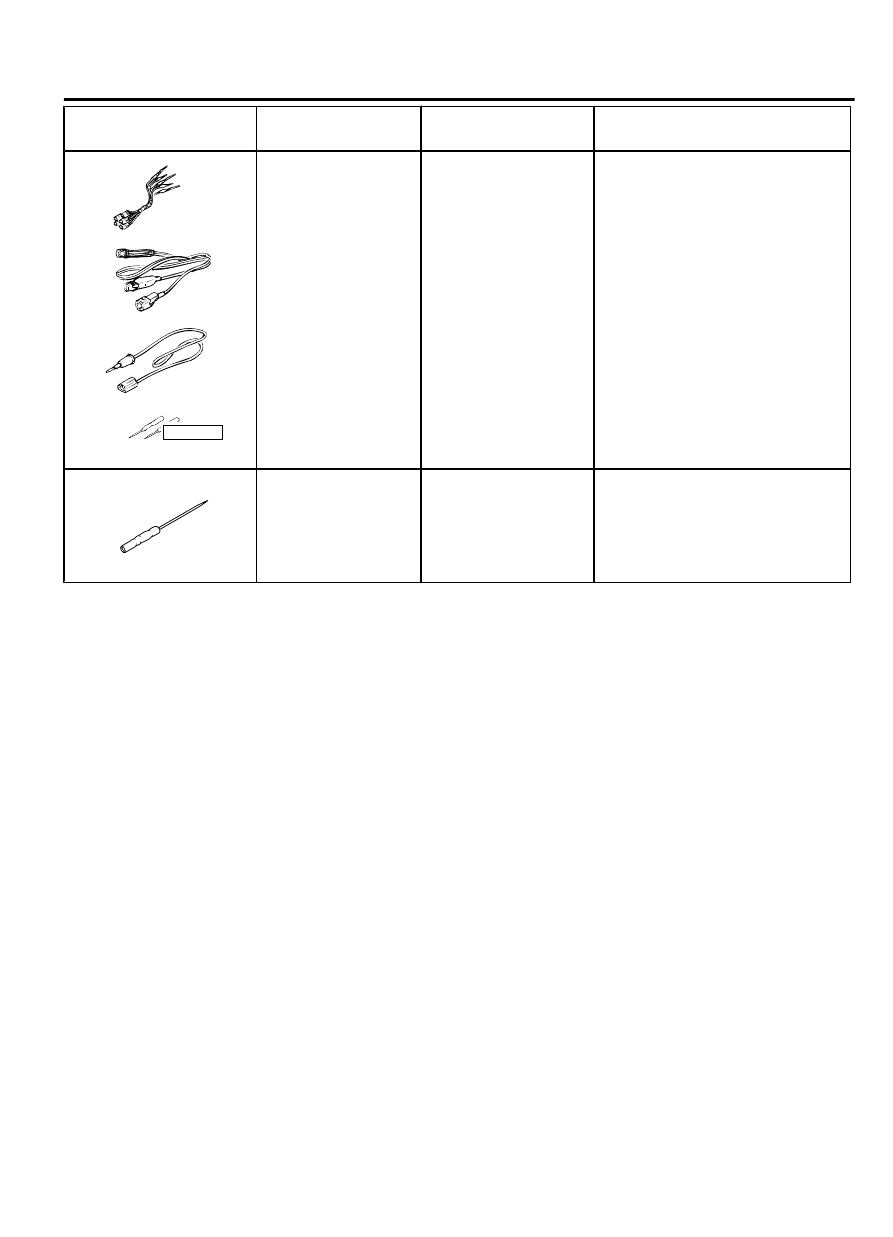


Tool

Tool  number  and
name

Supersession

Application

YB9912230000

Do not use

a

b

c

d

MB991223

a.

MB991219

b.

MB991220

c.

MB991221

d.

MB991222

Harness set

a.

Test harness

b.

LED harness

c.

LED

 harness

adaptor

d.

Probe

General service tools Continuity  check  and  voltage

measurement  at  harness  wire  or
connector

a.

Connector

 pin

 contact

pressure inspection

b.

Power circuit inspection

c.

Power circuit inspection

d.

Commercial tester connection

MB992006

MB992006
Extra fine probe

-

Continuity  check  and  voltage
measurement  at  harness  wire  or
connector.

DIAGNOSIS

STANDARD FLOW OF DIAGNOSTIC TROUBLESHOOTING

M15410000004USA0000010000

Refer to GROUP 00 - Contents of troubleshooting P.
00-6.

DIAGNOSTIC FUNCTION

M15410000020USA0000010000

HOW TO CONNECT THE SCAN TOOL (M.U.T.-III)

Required Special Tools:

MB991958: Scan Tool (M.U.T.-III Sub Assembly)

MB991824: Vehicle Communication Interface (V.C.I.)

MB991827: M.U.T.-III USB Cable

MB991910:  M.U.T.-III  Main  Harness  A  (Vehicles  with
CAN communication system)

IGNITION SWITCH

54Ag-3

DIAGNOSIS

ZC501967

AC404789

ZC5019680000

MB991824

MB991827

MB991910

Data link

connector

To prevent damage to scan tool MB991958, always turn the
ignition  switch  to  the  "LOCK"  (OFF)  position  before
connecting or disconnecting scan tool MB991958.

1.

Ensure that the ignition switch is at the "LOCK" (OFF) position.

2.

Start up the personal computer.

3.

Connect special tool MB991827 to special tool MB991824 and
the personal computer.

4.

Connect special tool MB991910 to special tool MB991824.

5.

Connect special tool MB991910 to the data link connector.

6.

Turn the power switch of special tool MB991824 to the "ON"
position.

NOTE: 

When special tool MB991824 is energized, special

tool MB991824 indicator light will be illuminated in a
green color.

7.

Start the M.U.T.-III system on the personal computer.

NOTE: 

Disconnecting scan tool MB991958 is the reverse of

the connecting sequence, making sure that the ignition
switch is at the "LOCK" (OFF) position.

HOW TO READ AND ERASE DIAGNOSTIC

TROUBLE CODES

Required Special Tools:

MB991958: Scan Tool (M.U.T.-III Sub Assembly)

MB991824: Vehicle Communication Interface (V.C.I.)

MB991827: M.U.T.-III USB Cable

MB991910:  M.U.T.-III  Main  Harness  A  (Vehicles  with
CAN communication system)

To prevent damage to scan tool MB991958, always turn the
ignition  switch  to  the  "LOCK"  (OFF)  position  before
connecting or disconnecting scan tool MB991958.

NOTE: 

If the battery voltage is low, diagnostic trouble

codes will not be set. Check the battery if scan tool
MB991958 does not display.

1.

Connect scan tool MB991958 to the data link connector.

2.

Turn the ignition switch to the "ON" position.

3.

Select "System select" from the start-up screen.

4.

Select "From 2006 MY" of "Model Year." When the "Vehicle
Information" is displayed, check the contents.

5.

Select  "ETACS"  from  "System  List",  and  press  the  "OK"
button.

NOTE: 

When the "Loading Option Setup" list is displayed,

check the applicable item.

6.

Select "Diagnostic Trouble Code."

7.

If a DTC is set, it is shown.

8.

Choose "Erase DTCs" to erase the DTC.

54Ag-4

IGNITION SWITCH

DIAGNOSIS

HOW TO DIAGNOSE THE CAN BUS LINES

Required Special Tools:

MB991958: Scan Tool (M.U.T.-III Sub Assembly)

MB991824: Vehicles Communication Interface (V.C.I.)

MB991827: M.U.T.-III USB Cable

MB991910:  M.U.T.-III  Main  Harness  A  (Vehicles  with
CAN communication system)

1.

Connect scan tool MB991958 to the data link connector.

2.

Turn the ignition switch to the "ON" position.

3.

Select "CAN bus diagnosis" from the start-up screen.

4.

When  the  vehicle  information  is  displayed,  confirm  that  it
matches the vehicle being diagnosed.

If they match, go to step 8.

If not, go to step 5.

5.

Select the "view vehicle information" button.

6.

Enter the vehicle information and select the "OK" button.

7.

When the vehicle information is displayed, confirm again that
it matches the vehicle being diagnosed.

If they match, go to step 8.

If not, go to step 5.

8.

Select the "OK" button.

9.

When the optional equipment screen is displayed, choose the
one which the vehicle is fitted with, and then select the "OK"
button.

TROUBLE SYMPTOM CHART

M15410000005USA0000010000

Trouble symptom

Reference
page

Ignition key cylinder illumination light does not illuminate/extinguish
normally.

vehicles with WCM

 P.54Ag-5

vehicles with KOS

 P.54Ag-9

SYMPTOM PROCEDURES

Ignition key cylinder illumination light does not illuminate/extinguish normally.
<vehicles with WCM>

M15410000018USA0000010000

Whenever  the  ECU  is  replaced,  ensure  that  the
input and output signal circuits are normal.

IGNITION SWITCH

54Ag-5

DIAGNOSIS

Ignition Key Cylinder Illumination Light Circuit 

KEY
REMINDER
SWITCH
WHEN
REMOVING
KEY: ON

IGNITION KEY
CYLINDER
ILLUMINATION
LIGHT

ETACS-ECU

ZC6008770002

Connector: C-211

ZC6008780008

Connector: C-315

OPERATION
The  ETACS-ECU  operates  this  function  in
accordance with the input signals below.

Ignition switch (IG1)

Key reminder switch

Driver's door switch

TECHNICAL DESCRIPTION (COMMENT)
If  this  function  does  not  work  normally,  these  input
signal circuit(s), the ignition key cylinder illumination
light or the ETACS-ECU may be defective.

54Ag-6

IGNITION SWITCH

SYMPTOM PROCEDURES


Content   ..  1071  1072  1073  1074   ..