Mitsubishi Outlander XL. Manual - part 1069


  Index      Mitsubishi     Mitsubishi Outlander XL - service repair manual 2007 year


Search            


Content   ..  1067  1068  1069  1070   ..


Mitsubishi Outlander XL. Manual - part 1069


The wiring harness or connectors may have loose,
corroded,  or  damaged  terminals,  or  terminals
pushed back in the connector

DIAGNOSIS

Required Special Tools:

MB992006: Extra fine probe

MB991223: Harness set

MB991958: Scan Tool (M.U.T.-III Sub Assembly)

MB991824: Vehicle Communication Interface (V.C.I.)

MB991827: M.U.T.-III USB Cable

MB991910:  M.U.T.-III  Main  Harness  A  (Vehicles  with
CAN communication system)

STEP 1. Using scan tool MB991958, read the diagnostic
trouble code.
Check if DTC is set to the ETACS-ECU.

ZC501967

AC404789

ZC5019680000

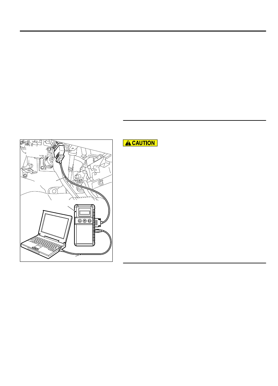
MB991824

MB991827

MB991910

Data link

connector

To prevent damage to scan tool MB991958, always turn the
ignition  switch  to  the  "LOCK"  (OFF)  position  before
connecting or disconnecting scan tool MB991958.

(1)

Connect scan tool MB991958. Refer to "How to connect scan
too (M.U.T.-III) P.54Af-4."

(2)

Turn the ignition switch to the "ON" position.

(3)

Check whether the ETACS-ECU related DTC is set.

(4)

Turn the ignition switch to the "LOCK" (OFF) position.

Q:Is the DTC set?

YES:

 Diagnose the ETACS-ECU. Refer to GROUP 54Ad,

Diagnosis P.54Ad-8.

NO:

 Go to Step 2.

STEP 2. Using scan tool MB991958, Check the configuration
function.

(1)

Turn the ignition switch to the "ON" position.

(2)

Use the ETACS-ECU configuration function to check that the
"Alarm" is set to "Enable".

(3)

Turn the ignition switch to the "LOCK" (OFF) position.

Q:Is the "Alarm" set to "Enable"?

YES:

 Go to Step 3.

NO:

 Use the ETACS-ECU configuration function to set the

"Alarm" to "Enable" (Refer to P.54Af-27).

ALARM SYSTEM

54Af-17

DIAGNOSIS

STEP 3. Check theft-alarm horn relay connector A-17X for
loose, corroded or damaged terminals, or terminals pushed
back in the connector.

Q:Is  theft-alarm  horn  relay  connector  A-17X  in  good

condition?

YES:

 Go to Step 4.

NO:

 Repair the damaged parts.

STEP 4. Check the theft-alarm horn relay.
Refer to P.54Af-29.

Q:Is the theft-alarm horn relay in good condition

YES:

 Go to Step 5.

NO:

 Replace the theft-alarm horn relay.

STEP 5. Measure the voltage at theft-alarm horn relay A-17X.

(1)

Remove the relay, and measure at the relay box side.

ZC5010400017

Relay box side: A-17X

(2)

Measure  the  voltage  between  theft-alarm  horn  relay
connector A-17X (terminal No. 1,4) and the body ground.

The  voltage  should  measure  approximately  12  volts
(battery positive voltage).

Q:Is the measured voltage approximately 12 volts (battery

positive voltage)?

YES:

 Go to Step 7.

NO:

 Go to Step 6.

STEP 6. Check the Wiring harness between theft-alarm horn
relay connector A-17X (terminal No. 1,4) and fusible link
(36).
Check the power supply line for open circuit and short circuit.

Q:Is the check result normal?

YES:

 The trouble can be an intermittent malfunction

(Refer to GROUP 00, How to use Troubleshooting/inspection
Service Points - How to Cope with Intermittent
Malfunction P.00-15).

NO:

 Repair the wiring harness.between theft-alarm horn

relay connector A-17X and fusible link (36).

STEP 7. Check theft-alarm horn connector A-58 for loose,
corroded or damaged terminals, or terminals pushed back
in the connector.

Q:Is theft-alarm horn connector A-58 in good condition?

YES:

 Go to Step 8.

NO:

 Repair the damaged parts.

STEP 8. Check the Wiring harness between theft-alarm horn
connector A-58 (terminal No. 1) and theft-alarm horn relay
connector A-17X (terminal No. 3).
Check the output lines for open circuit and short circuit.

NOTE: 

Before the wiring harness check, check intermediate

connector A-03, and then repair them if necessary.

54Af-18

ALARM SYSTEM

DIAGNOSIS

Q:Is the check result normal?

YES:

 Go to Step 9.

NO:

 Repair the wiring harness between theft-alarm horn

connector A-58 and theft-alarm horn relay connector
A-17X.

STEP 9. Check ETACS-ECU connector C-312 for loose,
corroded or damaged terminals, or terminals pushed back
in the connector.

Q:Is ETACS-ECU connector C-312 in good condition?

YES:

 Go to Step 10.

NO:

 Repair the damaged parts.

STEP 10. Check the Wiring harness between theft-alarm
horn relay connector A-17X (terminal No. 2) and ETACS-
ECU connector C-312 (terminal No. 15).
Check the output lines for open circuit and short circuit.

Q:Is the check result normal?

YES:

 Go to Step 11.

NO:

 Repair the wiring harness between theft-alarm horn

relay connector A-17X and ETACS-ECU connector C-312.

STEP 11. Replace theft-alarm horn.

(1)

Replace the theft-alarm horn.

Q:Does the theft-alarm work normally?

YES:

 he trouble can be an intermittent malfunction (Refer

to GROUP 00, How to use Troubleshooting/inspection
Service Points - How to Cope with Intermittent
Malfunction P.00-15).

NO:

 Replace the ETACS-ECU.

Inspection Procedure 4: Horns do not sound while the theft-alarm system is triggered.

M15410300053USA0000010000

Before replacing the ECU, ensure that the power
supply  circuit,  the  ground  circuit  and  the
communication circuit are normal.

ALARM SYSTEM

54Af-19

DIAGNOSIS

Horn Circuit

ETACS-ECU

RELAYBOX

FUSIBLE
LINK

36

HORN
RELAY

HORN
(LO)

HORN
(HI)

ENGINE
COMPARTMENT

ZC600878003

Connector: C-312

C-312

54Af-20

ALARM SYSTEM

DIAGNOSIS


Content   ..  1067  1068  1069  1070   ..