Mitsubishi Outlander GS45X. Manual - part 972


  Index      Mitsubishi     Mitsubishi Outlander GS45X - service repair manual


Search            


Content   ..  970  971  972  973   ..


Mitsubishi Outlander GS45X. Manual - part 972


MULTIPORT FUEL INJECTION (MFI) DIAGNOSIS

TSB Revision

MULTIPORT FUEL INJECTION (MFI) <3.0L ENGINE>

13B-821

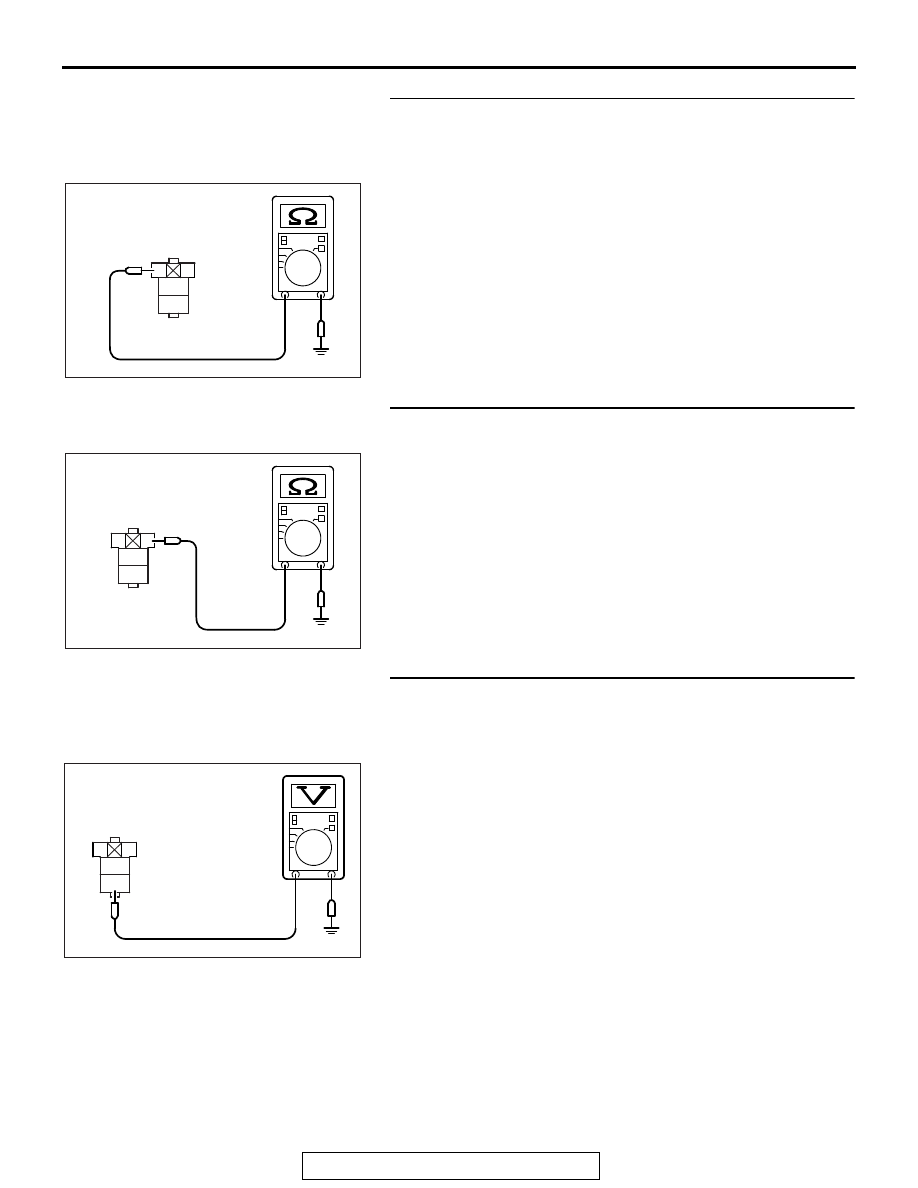
STEP 8. Check for short circuit to ground or harness 
damage between ECM connector B-10 and starter relay 
connector A-27X.
(1) Disconnect the B-10 and A-27X.
(2) Check for the continuity between connector A-27X (terminal 

No. 2) and ground.

• Not continuity.

Q: Is the harness wire in good condition?

YES : Go to Step 9.
NO :  Repair it. Then confirm that the malfunction symptom 

is eliminated.

STEP 9. Check for open circuit or harness damage 
between starter relay connector A-27X and ground.
(1) Disconnect the connector A-27X and ground at the harness 

side.

(2) Measure the resistance between connector A-27X (terminal 

No. 1) and ground.

• Should be less than 2 ohms.

Q: Is the measured resistance less than 2 ohms?

YES : Then go to Step 10.
NO :  Repair it. Then confirm that the malfunction symptom 

is eliminated.

STEP 10. Measure the power supply voltage at starter relay 
connector A-27X.
(1) Disconnect the connector A-27X measure at the harness 

side.

(2) Measure the voltage between terminal No. 4 and ground.

• Voltage should be battery positive voltage.

Q: Is battery positive voltage (approximately 12 volts) 

present?
YES : 
Go to Step 11.
NO :  Repair harness wire between starter relay connector 

A-27X (terminal No. 4) and fusible link (24) because 
of open circuit. Then confirm that the malfunction 
symptom is eliminated.

AK900613

2

1

3
4

AC

A-27X harness
connector:
component side 

AK700518

2

1

3
4

AB

A-27X harness
connector:
component side

2

1

3
4

AK700519AB

A-27X harness
connector:
component side

MULTIPORT FUEL INJECTION (MFI) DIAGNOSIS

TSB Revision

MULTIPORT FUEL INJECTION (MFI) <3.0L ENGINE>

13B-822

STEP 11. Check for open circuit or short circuit to ground 
or harness damage between starter relay connector A-27X 
and starter motor connector B-114.
(1) Disconnect the connector A-27X and B-114 measure at the 

harness side.

(2) Measure the resistance between connector A-27X (terminal 

No. 3) and connector B-114 (terminal No. 1).

• Should be less than 2 ohms.

(3) Check for the continuity between connector A-27X (terminal 

No. 3) and ground.

• Not continuity.

Q: Is the harness wire in good condition?

YES : Replace the starter motor. Then confirm that the 

malfunction symptom is eliminated.

NO :  Repair it. Then confirm that the malfunction symptom 

is eliminated.

1

2

1

3
4

AK700520AB

B-114 harness  connector:
component side

A-27X harness
connector:
component side

AK700521

2

1

3
4

AB

A-27X harness
connector:
component side

MULTIPORT FUEL INJECTION (MFI) DIAGNOSIS

TSB Revision

MULTIPORT FUEL INJECTION (MFI) <3.0L ENGINE>

13B-823

INSPECTION PROCEDURE 24: Ignition Circuit System.

AK800940

1

3

2

4

2 3

1

2 3

1

2 3

1

2 3

1

2 3

1

2 3

1

1

2 3

6

7 8

4 5

9 10

1

10 111213 14 1516 17 1819 20

2 3 4

5 6 7 8 9

1

2

3 4 5 6 7 8 9 10 11 12 13 14 15 16

17 18 19 20 21 22 23 24 25 26 27 28 29 30 31 32

33 34 35 36 37 38 39 40 41 42 43 44 45 46 47 48

49 50 51 52 53 54 55 56 57 58 59 60 61 62 63 64

AB

IGNITION CIRCUIT

1

2

5

21

4

20

52

4

16

1

A-13

B-21

MU802645

B-10

1

3

3

3

3

3

3

2

1

2

1

2

2

1

1

2

2

3

5

10A

A-33X

4

3

1

2

21

TO ECM

36

FUSIBLE LINK

WHITE

WHITE-

RED

WHITE-

RED

WHITE-

RED

WHITE-

RED

WHITE-

RED

WHITE-

RED

WHITE-BLUE

WHITE-RED

WHITE-GREEN

BLA

CK

BLA

CK

BLA

CK

BLA

CK

BLA

CK

BLA

CK

BLA

CK-WHITE

WHITE

WHITE

WHITE-BLA

CK

WHITE-

BLA

CK

BLA

CK-

WHITE

BLA

CK-RED

WHITE-RED

WHITE-RED

WHITE

OFF

ON

B-19

(MU802076)

B-18

(MU802076)

B-15

(MU802076)

B-05

(MU802076)

B-01

(MU802076)

B-04

(MU802076)

ENGINE CONTROL MODULE

RELAY BOX
(ENGINE COMPARTMENT)

IGNITION
COIL 2

IGNITION
COIL 4

IGNITION
COIL 6

IGNITION
COIL 1

IGNITION
COIL 3

IGNITION
COIL 5

MFI
RELAY

SPARK
PLUG

SPARK
PLUG

SPARK
PLUG

SPARK
PLUG

BLACK

SPARK
PLUG

SPARK
PLUG

53

WHITE-RED

BLACK

BLACK

MULTIPORT FUEL INJECTION (MFI) DIAGNOSIS

TSB Revision

MULTIPORT FUEL INJECTION (MFI) <3.0L ENGINE>

13B-824

.

CIRCUIT OPERATION

• The battery positive voltage is applied from the 

MFI relay (terminal No. 2) to the ignition coil (ter-
minal No.3) and is grounded to the vehicle body 
via the ignition coil (terminal No.1).

• A power voltage of 12 V is applied to the ignition 

coil (terminal No. 2) from the ECM (terminal No. 
4, No. 5, No. 20, No. 21, No. 52 and No. 53).

.

COMMENT

• When the ECM turn the power transistor in the 

unit to OFF, the battery positive voltage is applied 
to the power transistor in the ignition coil, result-
ing that the power transistor is ON. And, when 
the ECM turns the power transistor in the unit to 
ON, the power transistor in the ignition coil will be 
turned OFF.

• When the power transistor in the ignition coil is 

turned to ON with any signal from the ECM, the 
primary voltage will be applied through the igni-
tion coil.When the power transistor in the ignition 
coil is turned OFF, the primary current is blocked 
and high voltage is generated in the secondary 
coil.

.

TROUBLESHOOTING HINTS (The most 
likely causes for this case:)

• Malfunction of the ignition coil.

• Improper connector contact, open circuit or 

short-circuit harness wire.

• Malfunction of the ECM.

AK900602

Connector: A-13

A-13

AB

AK900134

AD

B-21 (B)

Connector: B-21

Intermediate
connector

AK700399AB

MFI relay

A-33X

Connector: A-33X

AK900146 AD

B-19 (B)

B-15 (B)

B-18 (B)

B-01 (B)

B-05 (B)

B-04 (B)

Connectors: B-01, B-04, B-05, B-15, B-18 and 
                      B-19

AK700401AB

ECM

B-10 (GR)

Connector: B-10


Content   ..  970  971  972  973   ..