Mitsubishi Outlander GS45X. Manual - part 862
 

  Index      Mitsubishi     Mitsubishi Outlander GS45X - service repair manual


Search            


Content   ..  860  861  862  863   ..


Mitsubishi Outlander GS45X. Manual - part 862


MULTIPORT FUEL INJECTION (MFI) DIAGNOSIS

TSB Revision

MULTIPORT FUEL INJECTION (MFI) <3.0L ENGINE>

13B-381

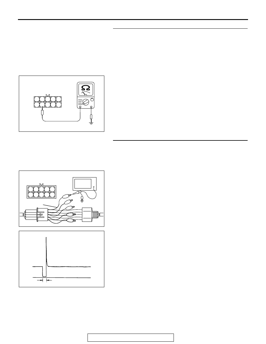
STEP 7. Check for harness between the intermediate 
connector B-21and the ECM connector B-10.
(1) Disconnect the intermediate connector B-21 and the ECM 

connector B-10.

(2) Measure the resistance between the intermediate 

connector B-21 (terminal No. 9) and the ECM connector 
B-10 (terminal No. 50).

• Should be less than 2 ohms.

(3) Measure the continuity between the intermediate connector 

B-21 (terminal No. 9) and ground.

• Not continuity

Q: Is the harness wire in good condition?

YES : Go to Step 8.
NO :  Repair it. Refer to GROUP 00E, Harness Connector 

Inspection 

P.00E-2

. Then go to Step 9.

STEP 8. Using the oscilloscope, check the No. 5 cylinder 
injector.
(1) Disconnect the intermediate connector B-21 and connect 

the test harness MB991658 between the separated 
connectors.

(2) Connect the oscilloscope probe to injector intermediate 

connector terminal to No. 9.
NOTE: When measuring with the ECM side connector, dis-
connect all ECM connectors. Connect the check harness 
special tool (MB992110) between the separated connec-
tors. Then connect an oscilloscope probe to the check har-
ness connector terminal No. 50.

(3) Start the engine and run at idle.

(4) Measure the waveform.

• The waveform should show a normal pattern similar to 

the illustration.

(5) Turn the ignition switch to the "LOCK" (OFF) position.
Q: Is the waveform normal?

YES : It can be assumed that this malfunction is intermittent. 

Refer to GROUP 00, How to Use 
Troubleshooting/Inspection Service Points 

− How to 

Cope with Intermittent Malfunctions 

P.00-15

.

NO :  Replace the ECM. When the ECM is replaced, 

register the ID code. Refer to GROUP 42B, Diagnosis 
− ID Codes Registration Judgment Table <Vehicles 

with KOS> 

P.42B-15

 or GROUP 42C, Diagnosis 

− ID 

Codes Registration Judgment Table <Vehicles with 
WCM> 

P.42C-10

. Then go to Step 9.

AK700307

1

2

3

4

5

6

7

8

9

10

AB

B-21 harness
connector:
component side

5

4

3

2

1

10

9

8

7

6

AK700300AB

B-21 Intermediate
connector

MB991658

Oscilloscope

AK700301

Normal waveform

A: Injector drive time

A

AB

MULTIPORT FUEL INJECTION (MFI) DIAGNOSIS

TSB Revision

MULTIPORT FUEL INJECTION (MFI) <3.0L ENGINE>

13B-382

STEP 9. Test the OBD-II drive cycle.
(1) Carry out a test drive with the drive cycle pattern. Refer to 

Diagnostic Function 

− OBD-II Drive Cycle − Pattern 22 

P.13B-11

.

(2) Check the diagnostic trouble code (DTC).
Q: Is DTC P0205 set?

YES : Retry the troubleshooting.
NO :  The inspection is complete.

MULTIPORT FUEL INJECTION (MFI) DIAGNOSIS

TSB Revision

MULTIPORT FUEL INJECTION (MFI) <3.0L ENGINE>

13B-383

DTC P0206: Injector Circuit - Cylinder 6

AK700148

1

3

2

4

1

2

3
4

1

2

3 4 5 6 7 8 9 10 11 12 13 14 15 16

17 18 19 20 21 22 23 24 25 26 27 28 29 30 31 32

33 34 35 36 37 38 39 40 41 42 43 44 45 46 47 48

49 50 51 52 53 54 55 56 57 58 59 60 61 62 63 64

1 2 3 4

5 6 7

15

14

13

12

11

9

8

1

6

4

5

9

8

10

10

11

13

15

14

12

16

7

2 3

2

1

1

10 111213 14 1516 17 1819 20

2 3 4

5 6 7 8 9

B-115

(MU802062)

1

2

ENGINE CONTROL MODULE

ETACS-
ECU

51

BLUE

RED-GREEN

B-10

AB

20A

WHITE

WHITE

A-33X

4

3

1

2

22

OFF

ON

WHITE

RED-WHITE

4

1

10

6

7

C-304

C-317

A-13

A-24X

3

BLUE

2

OFF

ON

WHITE

36

FUSIBLE LINK

INJECTOR CIRCUIT-CYLINDER 6

BLA

CK

BLA

CK

BLA

CK

IGNITION
SWITCH (IG1)

INJECTOR
RELAY

RELAY BOX
(ENGINE COMPARTMENT)

TO ECM

MFI
RELAY

INJECTOR
NO. 6

MULTIPORT FUEL INJECTION (MFI) DIAGNOSIS

TSB Revision

MULTIPORT FUEL INJECTION (MFI) <3.0L ENGINE>

13B-384

.

CIRCUIT OPERATION

• The injector power is supplied from the injector 

relay (terminal No. 3).

• The ECM controls the injector by turning the 

power transistor in the ECM "ON" and "OFF".

.

TECHNICAL DESCRIPTION

• The amount of fuel injected by the injector is con-

trolled by the amount of continuity time the coil is 
grounded by the ECM.

.

DESCRIPTIONS OF MONITOR METHODS

The ECM detects open circuit and short malfunction.

.

MONITOR EXECUTION

Continuous

.

AK900142AD

Connector: B-115

B-115 (GR)

AK700399AB

MFI relay

A-33X

Connector: A-33X

AK700401AB

ECM

B-10 (GR)

Connector: B-10

AK700413AB

A-24X

Connector: A-24X

Injector relay

AK700414 AB

ETACS-ECU

C-317

Connectors: C-304, C-317

C-304

AK900602

Connector: A-13

A-13

AB


Content   ..  860  861  862  863   ..