Mitsubishi Outlander GS45X. Manual - part 738


  Index      Mitsubishi     Mitsubishi Outlander GS45X - service repair manual


Search            


Content   ..  736  737  738  739   ..


Mitsubishi Outlander GS45X. Manual - part 738


MULTIPORT FUEL INJECTION (MFI) DIAGNOSIS

TSB Revision

MULTIPORT FUEL INJECTION (MFI) <2.4L ENGINE>

13A-775

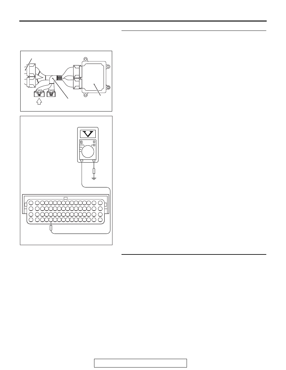
STEP 1. Measure the voltage at ECM connector B-10 by 
using poor plant ECU check harness special tool 
MB992110.
(1) Disconnect all ECM connectors. Connect the power plant 

ECU check harness special tool MB992110 between the 
separated connectors.

(2) Start the engine and run at idle.

(3) Measure the voltage between terminal No. 60 and ground.

NOTE: Vehicle for Canada, the headlight, taillight, etc. 
remain lit even when the lighting switch is in "OFF" position 
but this is no problem for checks.

a. Engine: warming up, idling
b. Radiator fan: stopped

c. Headlight: OFF to ON

d. Stop light: OFF to ON
e. Rear defogger switch: OFF to ON

• Voltage increases

(4) Turn the ignition switch to the "LOCK" (OFF) position.
Q: Is the measured voltage within the specified range?

YES : Go to Step 2.
NO :  Replace the generator. Then confirm that the 

malfunction symptom is eliminated.

STEP 2. Check harness connector B-10 at ECM connector 
and harness connector B-118 at generator connector for 
damage.
Q: Is the harness connector in good condition?

YES : Go to Step 3.
NO :  Repair or replace it. Refer to GROUP 00E, Harness 

Connector Inspection 

P.00E-2

. Then confirm that the 

malfunction symptom is eliminated.

AK604040

ECM

AB

Body side harness 

MB992110

AK604041

16 15 14 13 12 11 10 9 8 7 6 5 4 3

2

1

32 31 30 29 28 27 26 25 24 23 22 21 20 19 18 17

48 47 46 45 44 43 42 41 40 39 38 37 36 35 34 33

64 63 62 61 60 59 58 57 56 55 54 53 52 51 50 49

AC

Power plant ECU
check harness connector

MULTIPORT FUEL INJECTION (MFI) DIAGNOSIS

TSB Revision

MULTIPORT FUEL INJECTION (MFI) <2.4L ENGINE>

13A-776

STEP 3. Check for short circuit to ground between 
generator connector B-118 (terminal No. 1) and ECM 
connector B-10 (terminal No. 60).
Q: Is the harness wire in good condition?

YES : Replace the ECM. When the ECM is replaced, 

register the ID code. Refer to GROUP 42B, Diagnosis 
− ID Code Registration Judgment Table <Vehicles 

with KOS> 

P.42B-15

 or GROUP 42C, Diagnosis 

− ID 

Codes Registration Judgment Table <Vehicles with 
WCM> 

P.42C-10

.

NO :  Repair it. Then confirm that the malfunction symptom 

is eliminated.

MULTIPORT FUEL INJECTION (MFI) DIAGNOSIS

TSB Revision

MULTIPORT FUEL INJECTION (MFI) <2.4L ENGINE>

13A-777

Inspection procedure 22: Power supply system and ignition switch-IG system

1

3

2

4

71 72 73 74 75 76 77 78 79 80 81 82

83 84 85 86 87 88 89 90 91 92 93 94

95 96 97 98 99

100 101 102 103 104

112 113 114

109

108

107

110 111

115 116

106

105

118

117

AKA00832

1 2 3
4 5 6

1

6

4

5

9

8

10 11

13

15

14

12

16

7

2 3

1 2 3 4

5 6 7

15

14

13

12

11

10

9

8

1

2 3

4

5 6

93

81

5

6

IG2

ST

LOCK

ACC

IG1

20A

WHITE

WHITE

WHITE

A-33X

4

3

1

2

6

ETACS-ECU

C-304

C-317

10

22

7.5A

2

OFF

ON

POWER SUPPLY AND IGNITION SWITCH-IG CIRCUIT

WHITE

WHITE

WHITE-BLUE

RED-BLA

CK

73

104

82

GND

GND

92

B-11

IGNITION SWITCH

2

AC

C-210

FUSIBLE LINK

36

ENGINE CONTROL MODULE

MFI
RELAY

BATTERY
BACKUP

POWER
SOURCE

BLA

CK-RED

BLA

CK-WHITE

RELAY BOX
(ENGINE COMPARTMENT)

A-66

(MU802755)

GROUND
(FRONT: LH)

RED-WHITE

VIOLET

MULTIPORT FUEL INJECTION (MFI) DIAGNOSIS

TSB Revision

MULTIPORT FUEL INJECTION (MFI) <2.4L ENGINE>

13A-778

.

CIRCUIT OPERATION

• Battery positive voltage is applied to the MFI 

relay (terminals No. 3, No. 4).

• When the ignition switch is turned to the "ON" 

position, battery positive voltage is applied to the 
ECM (terminal No. 92). When battery positive 
voltage is applied, the ECM turns the power tran-
sistor in the ECM "ON" and grounds the MFI relay 
coil. With this, the MFI relay turns "ON" the bat-
tery positive voltage is supplied to the ECM (ter-
minals No. 82) from the MFI relay (terminal No. 
2).

• A battery positive voltage is constantly supplied 

to the ECM (terminal No. 104) as the backup 
power.

• The ECM (terminals No. 81, No. 93) is grounded 

to the vehicle body.

.

COMMENT

• When the ignition switch "ON" signal is input into 

the ECM via ETACS-ECU, the ECM turns "ON" 
the MFI relay. This causes battery positive volt-
age to be supplied to the ECM, sensor and actua-
tor.

.

TROUBLESHOOTING HINTS (The most 
likely causes for this code to be set are:) 

• Malfunction of the ignition switch.

• Malfunction of the MFI relay.

• Open of shorted power supply and ignition 

Switch-IG circuit, harness damage, or connector 
damage.

• Malfunction of the ECM.

AK704088

MFI relay

AB

Connector: A-33X

A-33X

AKA00840

Connector: A-66

A-66 (GR)

AB

AK704097AB

Connector: B-11

B-11 (GR)

AK900601

Connector: C-210

C-210

AB

AK700414 AB

ETACS-ECU

C-317

Connectors: C-304, C-317

C-304


Content   ..  736  737  738  739   ..