Mitsubishi Outlander GS45X. Manual - part 724


  Index      Mitsubishi     Mitsubishi Outlander GS45X - service repair manual


Search            


Content   ..  722  723  724  725   ..


Mitsubishi Outlander GS45X. Manual - part 724


MULTIPORT FUEL INJECTION (MFI) DIAGNOSIS

TSB Revision

MULTIPORT FUEL INJECTION (MFI) <2.4L ENGINE>

13A-719

13A

SYMPTOM PROCEDURES

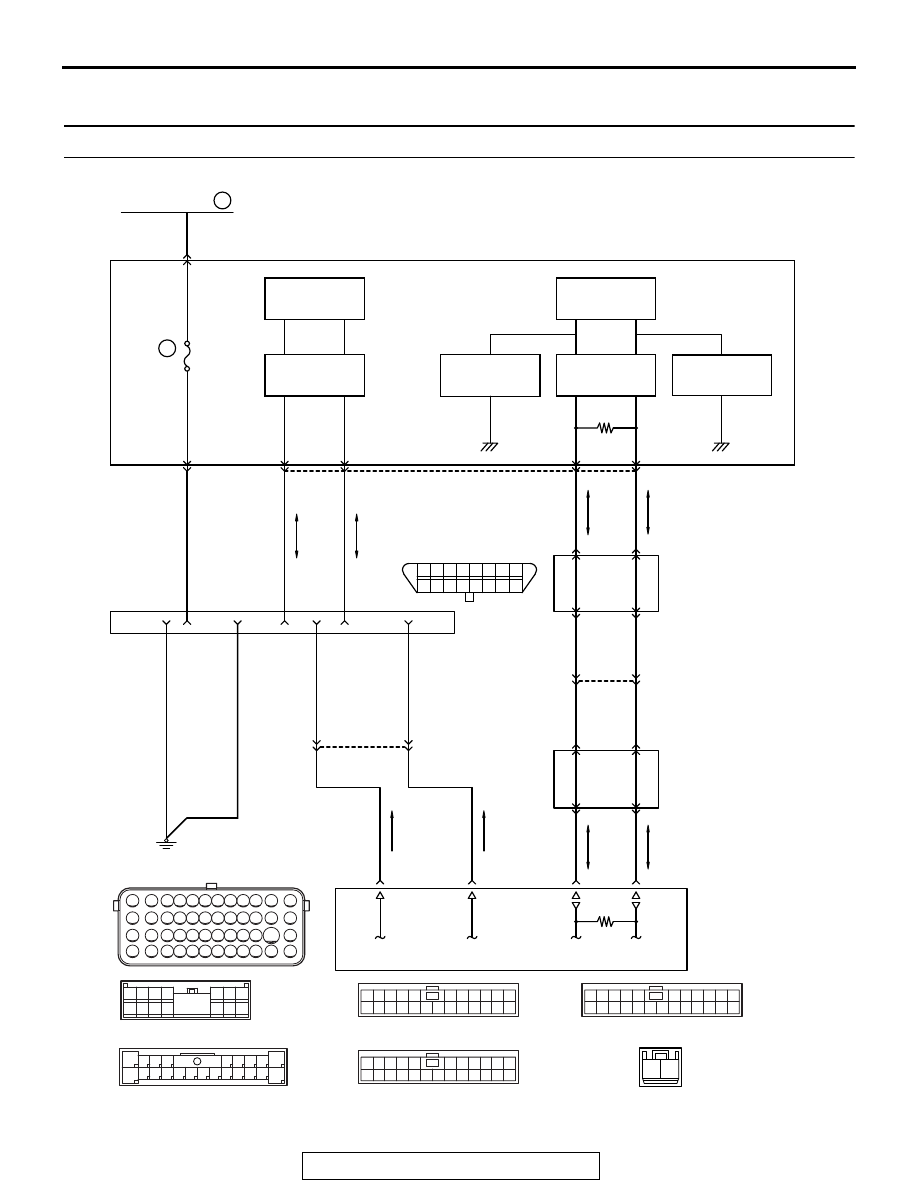
Inspection procedure 1: Communication with ECM only is not possible

71 72 73 74 75 76 77 78 79 80 81 82

83 84 85 86 87 88 89 90 91 92 93 94

95 96 97 98 99

100 101 102 103 104

112 113 114

109

108

107

110 111

115 116

106

105

118

117

1 2 3 4 5 6

12

11

10

1516

14

13

9

7 8

AKA00831

1

12 13 14 15 16 1718 19 20 2122 2324

2 3 4 5

6 7 8 9 10 11

1

12 13 14 15 16 1718 19 20 2122 2324

2 3 4 5

6 7 8 9 10 11

1

12 13 14 15 16 1718 19 20 2122 2324

2 3 4 5

6 7 8 9 10 11

2

8

7

6

5

4

3

11

21

20

19

18

17

16

15

14

13

12

9

22

1

10

1 2 3 4

5 6 7

15

14

13

12

11

10

9

8

1 2

FUSIBLE LINK

1

C-309

8

C-317

5

4

16

4

5

7

8

10

8

80

B-11

C-317

C-301

C-309

C-01

C-04

C-33

103

90

91

4

15

5

16

J/C (CAN3)
C-01

J/C (CAN2)
C-04

7

20

6

19

9

C-301

8

21

C-33

20

C-33

ENGINE
CONTROL
MODULE

DATA LINK
CONNECTOR

C-125

ETACS-ECU

6

14

10A

RED

WHITE

ORANGE

YELLO

W

PINK

BLA

CK

BLA

CK

YELLO

W

-GREEN

YELLO

W

-BLUE

YELLO

W

-BLUE

VIOLET

GREEN

GREEN-

WHITE

GREEN-

WHITE

YELLO

W

GREEN-

RED

GREEN

34

5

CAN COMMUNICATION CIRCUIT

BLA

CK

ANALOG
INTERFACE 
CIRCUIT

ANALOG
INTERFACE 
CIRCUIT

INTERFACE 
CIRCUIT

INTERFACE 
CIRCUIT

CAN DRIVE 
CIRCUIT

CAN DRIVE 
CIRCUIT

AB

<< Previous

MULTIPORT FUEL INJECTION (MFI) DIAGNOSIS

TSB Revision

MULTIPORT FUEL INJECTION (MFI) <2.4L ENGINE>

13A-720

.

CIRCUIT OPERATION

• Battery voltage is applied to the diagnosis con-

nector (terminal No. 16).

• The diagnosis connector (terminal No. 4 and No. 

5) is grounded to the vehicle body.

.

COMMENT

• When the communication between M.U.T.-III and 

ECM is impossible, it can be suspected that the 
CAN bus line, power supply circuit of the diagno-
sis connector, and/or grounding circuit are defec-
tive.

• Communication can not be achieved either, if a 

wrong vehicle type is selected on M.U.T.-III.

.

TROUBLESHOOTING HINTS (The most 
likely causes for this case:) 

• Malfunction of the data link connector.

AK704097AB

Connector: B-11

B-11 (GR)

AK900599

Connector: C-01

C-01

AB

AK900600

Connector: C-04

C-04

AB

AK700435

AB

Data link connector

Brakepedal

C-125 (B)

Connector: C-125

AK900598

Connector: C-33

C-33

AB

AK700443AB

ETACS-ECU

C-317

Connectors: C-301, C-309 and C-317

C-301

C-309 (B)

MULTIPORT FUEL INJECTION (MFI) DIAGNOSIS

TSB Revision

MULTIPORT FUEL INJECTION (MFI) <2.4L ENGINE>

13A-721

• Open/short circuit or poor contact in the data link 

connector.

• Malfunction of the CAN communication.

• Malfunction of the scan tool.

• Malfunction of the ECM.

DIAGNOSIS

Required Special Tools:

• MB991958: Scan tool (M.U.T.-III Sub Assembly)

• MB991824: V.C.I.

• MB991827: USB Cable

• MB991910: Main Harness A

STEP 1. Check the vehicle communication interface (V.C.I.) 
MB991824 operations.
(1) Connect the Scan tool to the data link connector.
(2) When the power of V.C.I. is turned to ON, the indicator lamp 

of the V.C.I. illuminates in green.

• The indicator lamp of the V.C.I. illuminates in green.

Q: Is the indicator lamp of the V.C.I. illuminates in green?

YES : Go to Step 2.
NO :  Use scan tool, perform CAN bus line diagnosis.

STEP 2. Measure the battery positive voltage.
(1) Measure the battery positive voltage during cranking.

• The voltage should be 8 volts or more.

Q: Is the measured voltage 8 volts or more?

YES : Go to Step 3.
NO :  Check the battery. Refer to GROUP 54A, Battery 

− 

On-vehicle Service 

− Battery Check 

P.54A-7

. Then 

confirm that the malfunction symptom is eliminated.

STEP 3. Check harness connector C-125 at data link 
connector for damage.
Q: Is the harness connector in good condition?

YES : Go to Step 4.
NO :  Repair or replace it. Refer to GROUP 00E, Harness 

Connector Inspection 

P.00E-2

. Then confirm that the 

malfunction symptom is eliminated.

AK700568AB

MB991824

MB991827

MB991910

Data link
connector

MULTIPORT FUEL INJECTION (MFI) DIAGNOSIS

TSB Revision

MULTIPORT FUEL INJECTION (MFI) <2.4L ENGINE>

13A-722

STEP 4. Measure the power supply voltage at data link 
connector C-125.
(1) Measure voltage between terminal No. 16 and ground.

• Voltage should be battery positive voltage.

Q: Is battery positive voltage (approximately 12 volts) 

present?
YES : 
Go to Step 5.
NO :  Repair an open circuit between ETACS-ECU 

connector C-317 (terminal No. 8) and data link 
connector C-125 (terminal No. 16). Then confirm that 
the malfunction symptom is eliminated.

STEP 5. Check the continuity at data link connector C-125.
(1) Check for the continuity between terminal No. 4, No. 5 and 

ground.

• Should be less than 2 ohms.

Q: Does continuity exist?

YES : Check and replace the scan tool. Then confirm that 

the malfunction symptom is eliminated.

NO :  Repair an open circuit or harness damage between 

data link connector C-125 (terminal No. 4, No. 5) and 
ground. Then confirm that the malfunction symptom is 
eliminated.

Inspection procedure 2: The malfunction indicator lamp (SERVICE ENGINE SOON or check engine 
lamp) does not illuminate right after the ignition switch is turned to the "ON" position

.

CIRCUIT OPERATION

• The combination meter causes the malfunction 

indicator lamp (SERVICE ENGINE SOON or 
Check Engine Lamp) to illuminate immediately 
after the ignition switch is turned to the "ON" posi-
tion occurred.

.

TROUBLESHOOTING HINTS (The most 
likely causes for this case:) 

• Malfunction of the malfunction indicator lamp 

(SERVICE ENGINE SOON or Check Engine 
Lamp).

• Open or shorted malfunction indicator lamp 

(SERVICE ENGINE SOON or Check Engine 
Lamp) circuit.

AK700202

1 2 3 4 5 6 7 8

16

15

14

13

12

11

10

9

AB

C-125 harness
connector:
component side 

AK700203

1 2 3 4 5 6 7 8

16

15

14

13

12

11

10

9

AB

C-125 harness
connector:
component side 


Content   ..  722  723  724  725   ..