Mitsubishi Outlander GS45X. Manual - part 395
DIAGNOSIS
TSB Revision
ACTIVE STABILITY CONTROL SYSTEM (ASC)
35C-7
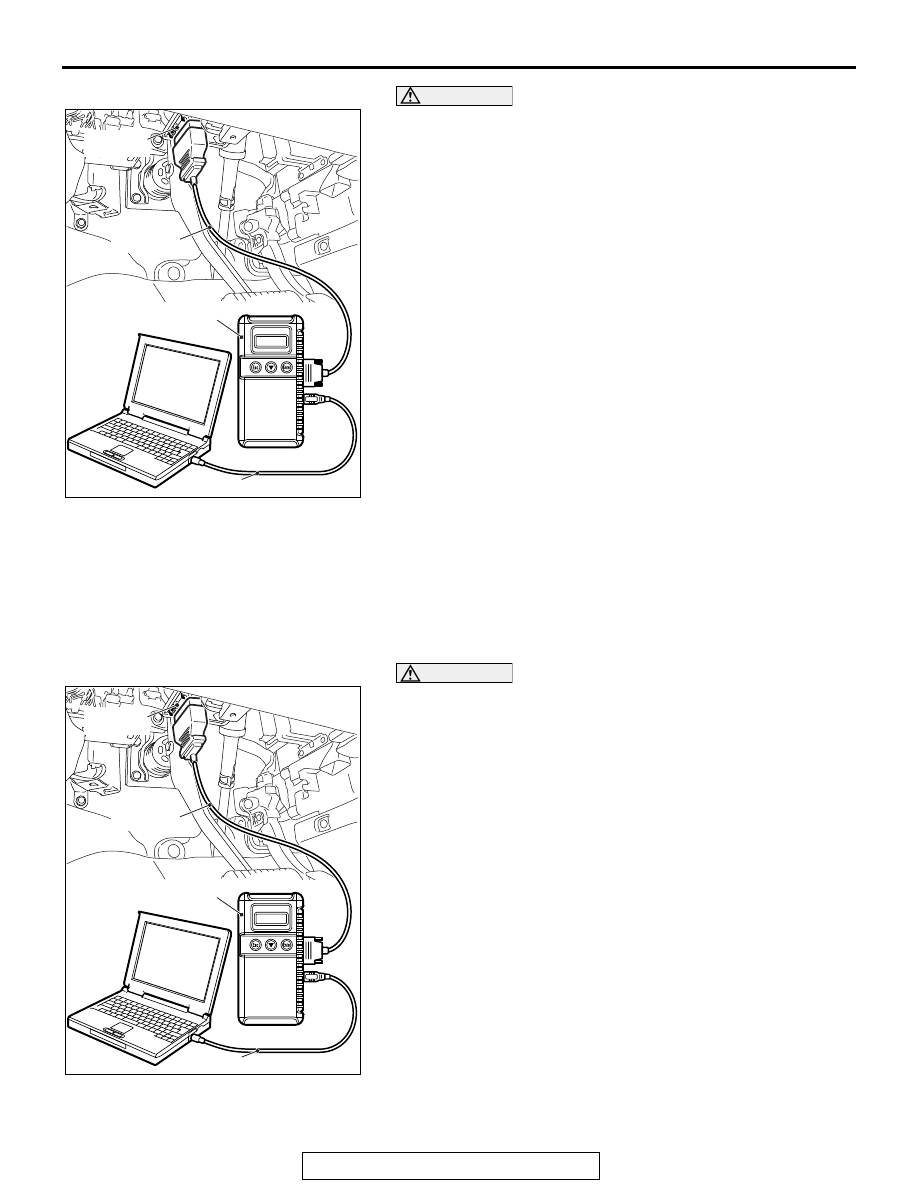
CAUTION
To prevent damage to scan tool MB991958, always turn the
ignition switch to the "LOCK" (OFF) position before con-
necting or disconnecting scan tool MB991958.
1. Connect scan tool MB991958 to the data link connector.
2. Turn the ignition switch to the "ON" position.
3. Select "System Select."
4. Select "ABS/ASC/ASTC" from the system list, and select the
"OK" button.
5. Choose "Actuator Test" from "ABS" screen.
6. Choose an appropriate item and select the "OK" button.
HOW TO DIAGNOSE THE CAN BUS LINE
Required Special Tools:
• MB991958: Scan Tool (M.U.T.-III Sub Assembly)
• MB991824: Vehicle Communication Interface (V.C.I.)
• MB991827: M.U.T.-III USB Cable
• MB991910: M.U.T.-III Main Harness A
CAUTION
To prevent damage to scan tool MB991958, always turn the
ignition switch to the "LOCK" (OFF) position before con-
necting or disconnecting scan tool MB991958.
1. Connect scan tool MB991958 to the data link connector.
2. Turn the ignition switch to the "ON" position.
3. Select "CAN bus diagnosis" from the start-up screen.
4. When the vehicle information is displayed, confirm that it
matches the vehicle whose CAN bus lines will be
diagnosed.
• If they match, go to step 8.
• If not, go to step 5.
5. Select "view vehicle information" button.
6. When the vehicle information is displayed, confirm again
that it matches the vehicle which is being diagnosed.
• If they match, go to step 8.
• If not, go to step 5.
7. Press the "OK" button.
8. When the options are displayed, choose the options (mark
the check) and then select "OK".
ZC501967
AC404789
AC701411AB
MB991824
MB991827
MB991910
Data link
connector
ZC501967
AC404789
AC701411AB
MB991824
MB991827
MB991910
Data link
connector