Mitsubishi Outlander GS45X. Manual - part 1540


  Index      Mitsubishi     Mitsubishi Outlander GS45X - service repair manual


Search            


Content   ..  1538  1539  1540  1541   ..


Mitsubishi Outlander GS45X. Manual - part 1540
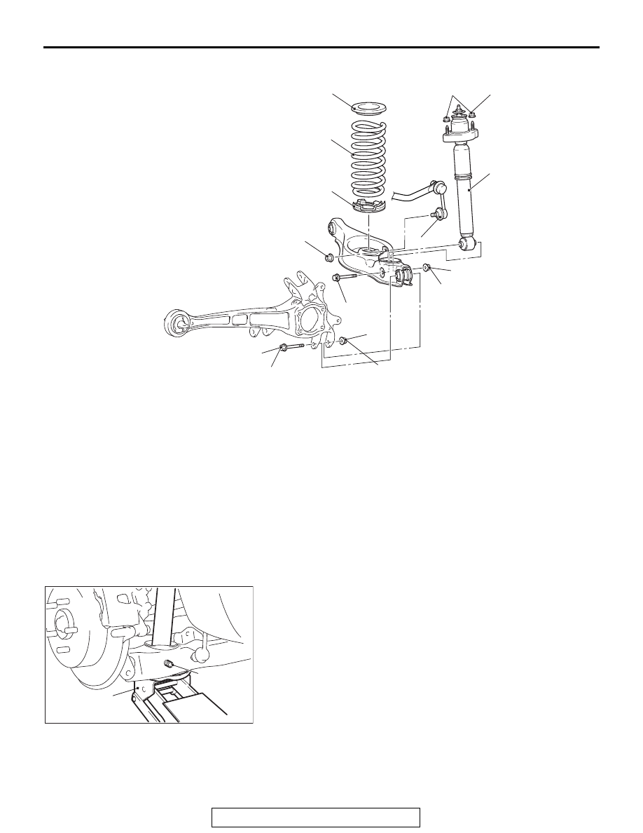


SHOCK ABSORBER ASSEMBLY

TSB Revision

REAR SUSPENSION

34-29

<2.4L ENGINE: 7 persons seat, 3.0L ENGINE>

REMOVAL SERVICE POINT

.

<<A>> LOWER ARM AND TRAILING ARM/SHOCK 
ABSORBER AND LOWER ARM DISCONNECTION

While jacking-up the lower arm with the garage jack, remove 
the mounting bolts.

.

AC608510

45 ± 7 N·m
33 ± 5 ft-lb

3

2

4

7

5

6

39 ± 6 N·m
29 ± 4 ft-lb

AD

1

8

71 ± 10 N·m
52 ± 2 ft-lb

*1

*1

71 ± 10 N·m
52 ± 2 ft-lb

*1

*1

*2

*2

*2

Shock absorber removal steps 

1.

Stabilizer link connection

<<

A

>>

2.

Lower arm and trailing arm 
connection

<<

A

>>

3.

Shock absorber and lower arm 
connection

<<

B

>>

4.

Shock absorber mounting nut

5.

Shock absorber assembly

Coil spring removal steps 

1.

Stabilizer link connection

<<

A

>>

2.

Lower arm and trailing arm 
connection

<<

A

>>

3.

Shock absorber and lower arm 
connection

6.

Coil spring

7.

Coil spring upper pad

8.

Coil spring lower pad

AC608511

Mounting 
bolt

AD

Garage 
jack

SHOCK ABSORBER ASSEMBLY

TSB Revision

REAR SUSPENSION

34-30

<<B>> SHOCK ABSORBER MOUNTING NUT 
REMOVAL

Remove the maintenance lid as shown in the figure, and then 
remove the shock absorber mounting nut.

INSTALLATION SERVICE POINT

.

>>A<< SHOCK ABSORBER ASSEMBLY INSTAL-
LATION

Install the shock absorber assembly so that the coil spring end 
faces the rear of the vehicle.

INSPECTION

M1341002600246

• Check the rubber parts for cracks and wear.

• Check the shock absorber for malfunctions, oil leakage, or 

abnormal noise.

AC507198

Maintenance lid

AB

AC508628AD

Spring end

SHOCK ABSORBER ASSEMBLY

TSB Revision

REAR SUSPENSION

34-31

DISASSEMBLY AND ASSEMBLY <2.4L ENGINE: 5 PERSONS SEAT>

M1341002700265

Required Special Tools:

• MB991793: Spring compressor

• MB991796: Attachment B

• MB991794: Upper plate

• MB991830: Fixture 

AC506862AB

1

2

3

4

5

6

7

8

9

10

11

25 ± 5 N·m
19 ± 3 ft-lb

Disassembly steps 

<<

A

>> >>

B

<< 1.

Self-locking nut

2.

Washer

3.

Bushing B

4.

Collar

5.

Spring upper bracket assembly

6.

Spring upper pad

7.

Bushing A

8.

Plate

9.

Bump rubber

>>

A

<< 10. Coil spring

11. Shock absorber

Disassembly steps (Continued)

SHOCK ABSORBER ASSEMBLY

TSB Revision

REAR SUSPENSION

34-32

DISASSEMBLY SERVICE POINTS

.

<<A>> SELF-LOCKING NUT REMOVAL

CAUTION

The locking nut for the piston rod inside the shock 
absorber may be loose. Do not use an impact wrench to 
loosen the self-locking nut.
1. Install the special tool MB991796 to the special tool 

MB991793 as shown in the figure.

2. Set the strut assembly to special tools: MB991793, 

MB991796, MB991794 and MB991830.
NOTE: Use the bolts and nuts removed from the vehicle to 
secure the shock absorber assembly and tighten them 
lightly by hand.

3. After setting the shock absorber assembly, operate the 

spring compressor and compress the coil spring by 
approximately 5 mm (0.20 in).

4. While holding the piston rod as shown in the figure, remove 

the self-locking nut.

.

AC209277AB

MB991796

MB991793

AC403179

MB991794

AB

MB991830

MB991796

MB991793

AC102268

AC708462 AC

Piston rod


Content   ..  1538  1539  1540  1541   ..