Mitsubishi Outlander GS45X. Manual - part 1473


  Index      Mitsubishi     Mitsubishi Outlander GS45X - service repair manual


Search            


Content   ..  1471  1472  1473  1474   ..


Mitsubishi Outlander GS45X. Manual - part 1473


SRS AIR BAG DIAGNOSIS

TSB Revision

SUPPLEMENTAL RESTRAINT SYSTEM (SRS)

52B-387

STEP 4. Battery check.
Refer to GROUP 54A, Battery Test 

P.54A-9

.

Q: Is the check result normal?

YES : Go to Step 5.
NO :  Charge (B210D only) or replace the battery.

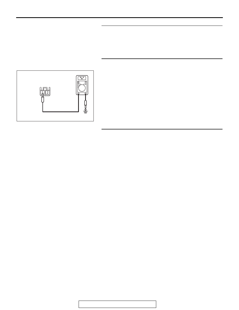
STEP 5. Measure the voltage at the ETACS-ECU connector.
(1) Disconnect the C-309 ETACS-ECU connector.
(2) Measure the voltage between the C-309 harness side 

connector terminal No. 1 and the body ground.

• The voltage should measure 12 volts (battery positive 

voltage).

Q: Is the measured voltage approximately 12 volts (battery 

positive voltage)?
YES : 
Go to Step 7.
NO :  Go to Step 6.

STEP 6. Wiring harness check between the fusible link (34) 
and the C-309 ETACS-ECU connector terminal No. 1.

•  Open circuit check for ETACS-ECU power supply wire

Q: Is the check result normal?

YES : Go to Step 10.
NO :  Repair the wiring harness.

AC709344

C-309 Harness side 
connector (rear view)

AE

SRS AIR BAG DIAGNOSIS

TSB Revision

SUPPLEMENTAL RESTRAINT SYSTEM (SRS)

52B-388

STEP 7. Using scan tool MB991958, diagnose the ETACS.

CAUTION

To prevent damage to scan tool MB991958, always turn the 
ignition switch to the "LOCK" (OFF) position before con-
necting or disconnecting scan tool MB991958.
(1) Connect scan tool MB991958. Refer to "How to connect the 

scan tool 

P.52B-28

."

(2) Erase the DTC.
(3) Turn the ignition switch to the "ON" position.
(4) Diagnose the CAN bus line.
(5) Turn the ignition switch to the "LOCK" (OFF) position.
Q: Is the CAN bus line found to be normal?

YES : Diagnose the ETACS (Refer to GROUP 54A, ETACS, 

Diagnosis 

P.54A-733

).

NO :  Check the input signal of ETACS-ECU ignition switch 

(IG1) (Refer to GROUP 54A 

− ETACS, Symptom 

procedures 

P.54A-789

). Than go to step 8.

STEP 8. Using scan tool MB991958, diagnose the CAN bus 
line.

CAUTION

To prevent damage to scan tool MB991958, always turn the 
ignition switch to the "LOCK" (OFF) position before con-
necting or disconnecting scan tool MB991958.
(1) Connect scan tool MB991958. Refer to "How to connect the 

scan tool 

P.52B-28

."

(2) Turn the ignition switch to the "ON" position.
(3) Diagnose the CAN bus line.
(4) Turn the ignition switch to the "LOCK" (OFF) position.
Q: Is the CAN bus line found to be normal?

YES : Go to Step 9.
NO :  Repair the CAN bus line (Refer to GROUP 54C, 

Diagnosis 

P.54C-17

).

ZC501967

AC404789

AC701411AB

MB991824

MB991827

MB991910

Data link 
connector

ZC501967

AC404789

AC701411AB

MB991824

MB991827

MB991910

Data link 
connector

SRS AIR BAG DIAGNOSIS

TSB Revision

SUPPLEMENTAL RESTRAINT SYSTEM (SRS)

52B-389

STEP 9. Recheck for diagnostic trouble code.
Check again if the DTC is set.
(1) Erase the DTC.
(2) Turn the ignition switch to "ON" position.
(3) Check if the DTC is set.
(4) Turn the ignition switch to the "LOCK" (OFF) position.
Q: Is the DTC set?

YES : Go to Step 10.
NO :  There is an intermittent malfunction such as poor 

engaged connector(s) or open circuit (Refer to 
GROUP 00, How to Cope with Intermittent 
Malfunction 

P.00-15

).

STEP 10. Recheck for diagnostic trouble code.
Check again if the DTC is set.
(1) Erase the DTC.
(2) Turn the ignition switch to the "ON" position.
(3) Check if the DTC is set.
(4) Turn the ignition switch to the "LOCK" (OFF) position.
Q: Is DTC B210D or B210E set?

YES : Replace the passenger seat cushion frame assembly 

(Refer to GROUP 52A, Front Seat Assembly 

P.52A-19

).

NO :  There is an intermittent malfunction such as poor 

engaged connector(s) or open circuit (Refer to 
GROUP 00, How to Cope with Intermittent 
Malfunction 

P.00-15

).

DTC B2206: Chassis number does not match

CAUTION

If DTC B2206 is set in the occupant classifica-
tion-ECU, always diagnose the CAN bus line.

.

TROUBLE JUDGMENT

If the registered chassis number is different from the 
chassis number transmitted on the CAN bus lines, 
the occupant classification-ECU sets the DTC 
B2206.

.

JUDGMENT CRITERIA

If the chassis number registered to occupant classifi-
cation-ECU and the chassis number on CAN bus 
lines do not match, the occupant classification-ECU 
determines that a problem has occurred.

.

TROUBLESHOOTING HINTS

• Chassis number not written

• The occupant classification-ECU may be defec-

tive.

• The CAN bus line may be defective.

DIAGNOSIS

Required Special Tools:

• MB991958: Scan Tool (M.U.T.-III Sub Assembly)

• MB991824: Vehicle Communication Interface (V.C.I.)

• MB991827: M.U.T.-III USB Cable

• MB991910: M.U.T.-III Main Harness A (Vehicles with 

CAN communication system)

SRS AIR BAG DIAGNOSIS

TSB Revision

SUPPLEMENTAL RESTRAINT SYSTEM (SRS)

52B-390

STEP 1. Using scan tool MB991958, diagnose the CAN bus 
line.

CAUTION

To prevent damage to scan tool MB991958, always turn the 
ignition switch to the "LOCK" (OFF) position before con-
necting or disconnecting scan tool MB991958.
(1) Connect scan tool MB991958. Refer to "How to connect the 

Scan Tool (M.U.T.-III) 

P.52B-28

."

(2) Turn the ignition switch to the "ON" position.
(3) Diagnose the CAN bus line.
(4) Turn the ignition switch to the "LOCK" (OFF) position.
Q: Is the CAN bus line found to be normal?

YES : Accuracy check is performed. Then go to Step 2.
NO :  Repair the CAN bus line (Refer to GROUP 54C, 

Diagnosis 

P.54C-17

).

STEP 2. Recheck for diagnostic trouble code.
Check again if the DTC is set to the occupant classifica-
tion-ECU.
(1) Zero calibration of occupant classification-ECU.
(2) Erase the DTC.
(3) Turn the ignition switch from "LOCK" (OFF) position to "ON" 

position.

(4) Check if DTC is set.
(5) Turn the ignition switch to the "LOCK" (OFF) position.
Q: Is the DTC set?

YES : Replace the passenger seat cushion frame assembly 

(Refer to GROUP 52A, Front Seat Assembly 

P.52A-17

).

NO :  There is an intermittent malfunction such as poor 

engaged connector(s) or open circuit (Refer to 
GROUP 00, How to Cope with Intermittent 
Malfunction 

P.00-15

).

ZC501967

AC404789

AC701411AB

MB991824

MB991827

MB991910

Data link 
connector


Content   ..  1471  1472  1473  1474   ..