Mitsubishi Outlander GS45X. Manual - part 1210


  Index      Mitsubishi     Mitsubishi Outlander GS45X - service repair manual


Search            


Content   ..  1208  1209  1210  1211   ..


Mitsubishi Outlander GS45X. Manual - part 1210


MAINTENANCE SERVICE

TSB Revision

GENERAL

00-83

<3.0L ENGINE>

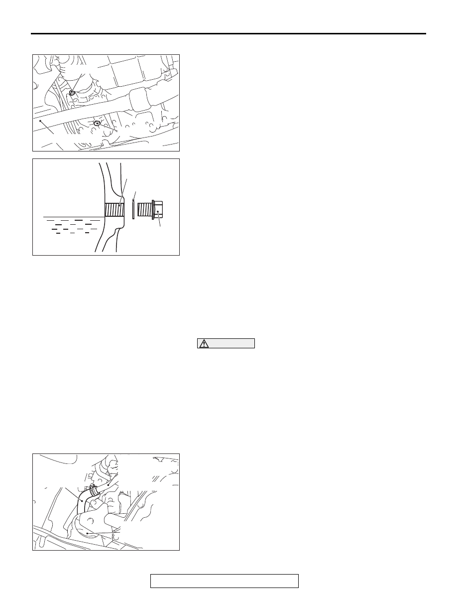
1. Remove the drain plug and gasket, to drain the transfer oil.
2. Install the drain plug and new gasket, and tighten to the 

specified torque.

Tightening torque: 32 

± 2 Nm (24 ± 1 ft-lb)

3.  Remove the filler plug and gasket and fill the transfer oil up 

to the lower edge of the filler plug hole.

Brand name: Hypoid gear oil API classification GL-5 

SAE 90

Filling amount: 0.53 dm

3

 (0.56 quarts)

4. Install the filler plug and new gasket and tighten to the 

specified torque.

Tightening torque: 32 

± 2 Nm (24 ± 1 ft-lb)

14. ENGINE COOLANT

M1001003100711

CHANGE

Check the cooling system parts such as the radiator, heater 
and oil cooler hoses, thermostat and their connections for leak-
age and damage.

WARNING

When removing the radiator cap, use care to avoid 
contact with hot engine coolant or steam. Place a 
shop towel over the radiator cap and turn the radiator 
cap counterclockwise a little to let the pressure 
escape through the vinyl tube. After relieving the 
steam pressure, remove the radiator cap by slowly 
turning it counterclockwise.

1. Drain the engine coolant from the radiator, heater core and 

engine after unplugging the radiator drain plug and removing 
the radiator cap.

2. Disconnect the water hose <M/T> or cooling water line hose 

<CVT>, and drain the engine coolant in the water jacket.

AC607764 AB

Filler plug

Drain plug

Front exhaust pipe

AC700330AG

Gasket

Transfer oil

Filler plug hole

Filler plug

AC506619AJ

Engine front
roll stopper
bracket

Water pipe 
assembly <M/T> or
CVT fluid cooler
water tube
assembly <CVT>

Water hose <M/T>
or cooling water
line hose <CVT>

MAINTENANCE SERVICE

TSB Revision

GENERAL

00-84

3. Drain the water in the water jacket by unplugging the drain 

plug of the cylinder block.

4. Remove the radiator condenser tank and drain the engine 

coolant.

5. Connect the water hose <M/T> or cooling water line hose 

<CVT>.

6. Replace the cylinder block drain plug gasket, and tighten the 

drain plug to the specified torque.

Tightening torque: 39 

± 3 Nm (29 ± 2 ft-lb)

7. Securely tighten the radiator drain plug.
8. Reinstall the radiator condenser tank.

CAUTION

Do not use alcohol or methanol anti-freeze or any engine 
coolants mixed with alcohol or methanol anti-freeze. The 
use of an improper anti-freeze can cause corrosion of the 
aluminum components.
9. Use special tool MB991871 to refill the engine coolant up to 

the top of the radiator port.

Recommended antifreeze: DIA QUEEN SUPER 

LONG LIFE COOLANT PREMIUM or equivalent*

*: similar high quality ethylene glycol based non-sili-

cate, non-amine, non-nitrate and non-borate cool-
ant with long life hybrid organic acid technology

Quantity: 7.5 dm

3

 (7.9 quarts)

[includes 0.65 dm

3

 (0.69 quarts) in the radiator con-

denser tank]

NOTE: For how to use special tool MB991871, refer to its 
manufacturer’s instructions.

10.Tighten the radiator cap securely.
11.Remove the radiator condenser tank cap, and add the 

engine coolant up to the "FULL" line.

12.Turn the A/C switch to OFF position to start the engine and 

warm up until the radiator fan operates.
NOTE: This work is to open the thermostat fully.

13.Rev the engine several times and then stop it. Check that 

there are no engine coolant leaks.

14.Remove the radiator cap with the engine cool, and then refill 

the engine coolant up to the top of the radiator port.

15.Tighten the radiator cap securely.

CAUTION

Do not overfill the radiator condenser tank.
16.Remove the radiator condenser tank cap, and add the 

engine coolant up to the "FULL" line.

AC612051AB

Exhaust side

AC611991AB

Cylinder block
drain plug

Gasket

AC609929

MB991871

Air hose

AB

MAINTENANCE SERVICE

TSB Revision

GENERAL

00-85

15. COOLANT HOSES (RADIATOR HOSE, 
HEATER HOSE) (INSPECT)

M1001009700186

Inspect the surface of radiator hoses and heater hoses for heat 
and mechanical damage. Hard and brittle rubber, cracking, 
tears, cuts, abrasions and excessive swelling indicate deterio-
ration of the rubber.

16. DISK BRAKE PADS, ROTORS (INSPECT FOR 
WEAR)

M1001003200611

.

BRAKE PAD CHECK

CAUTION

If there is a significant difference in thickness between the 
brake pads at right and left, check the sliding area and the 
runout of the brake disk (Refer to 

P.35A-24

).

1. Visually check the thickness of brake pad from the 

inspection hole of the caliper body.

Standard value: 10.0 mm (0.39 inch)
Limit: 2.0 mm (0.08 inch)

2. If the brake pad thickness is less than the limit value, 

replace the brake pad (Refer to 

P.35A-21

).

.

BRAKE DISK THICKNESS CHECK

1. Using a micrometer, measure disk thickness at eight 

positions, approximately 45 degrees apart and 10 mm (0.4 
inch) in from the outer edge of the disk.

Standard value:

26.0 mm (1.02 inch) <Front>
10.0 mm (0.39 inch) <Rear>

Limit:

24.4 mm (0.96 inch) <Front>
8.4 mm (0.33 inch) <Rear>

NOTE: Thickness variation (at least 8 positions) should not 
be more than 0.015 mm (0.0006 inch).

.

AC505542 AB

<Front>

AC505543 AB

<Rear>

ACX00668AB

MAINTENANCE SERVICE

TSB Revision

GENERAL

00-86

FRONT BRAKE DISK RUN-OUT CHECK AND 
CORRECTION

Place a dial gauge approximately 5 mm (0.2 inch) from the 
outer circumference of the brake disk, and measure the run-out 
of the disk.

Limit:

0.06 mm (0.0024 inch) <Front>
0.08 mm (0.0032 inch) <Rear>

17. BRAKE HOSES (CHECK FOR 
DETERIORATION OR LEAKS)

M1001003400499

Inspection of brake hoses should be included in all brake ser-
vice operations.
The hoses should be checked for:
1. Incorrect length, severe surface cracking, pulling, scuffing or 

worn spots. (If the fabric casing of the hoses is exposed by 
cracks or abrasion in the rubber hose cover, the hoses 
should be replaced. Eventual deterioration of the hose and 
possible bursting failure may occur).

2. Incorrect installation, twisting or interference with wheel, tire 

or chassis.

18. BALL JOINT AND STEERING LINKAGE 
SEALS (INSPECT FOR GREASE LEAKS AND 
DAMAGE)

M1001003500504

1. These components, which are permanently lubricated at the 

factory, do not require periodic lubrication. Damaged seals 
and bellows should be replaced to prevent leakage or 
grease contamination.

2. Inspect the dust cover and bellows for proper sealing, 

leakage and damage, and replace them if defective.

ACX00669AB

AC100948

Boot

Dust
cover

AC


Content   ..  1208  1209  1210  1211   ..