Mitsubishi Outlander (2013+). Manual - part 656
 

  Index      Mitsubishi     Mitsubishi Outlander - service repair manual 2013 year


Search            


Content   ..  654  655  656  657   ..


Mitsubishi Outlander (2013+). Manual - part 656


HEADLAMP

CHASSIS ELECTRICAL

54A-109

Inspection Procedure 14: The coming home light function does not work normally.

CAUTION

• Before replacing the ECU, ensure that the 

power supply circuit, the earth circuit and the 
communication circuit are normal.

• When the ETACS-ECU of vehicles without 

KOS is replaced, the encrypted code of the 
ignition key needs to be registered to the 
ETACS-ECU. (If the encrypted code is not reg-
istered, the engine cannot be started. Regis-
ter the encrypted code as described in 
Immobilizer System 

 How to Register Key ID 

P.54A-33

.)

COMMENTS ON TROUBLE SYMPTOM

When the coming home light function does not oper-
ate normally, the keyless entry system or the 
ETACS-ECU may have a problem. Or, the coming 
home light function may have been set to disabled 
using the customisation function.

PROBABLE CAUSES

• Malfunction of the keyless entry system

• Malfunction of the ETACS-ECU

DIAGNOSIS PROCEDURE

STEP 1. ETACS-ECU customise function check.
Check that any one of the followings other than "Dis-
abled" is set for "Coming home light" with a customi-
sation function.

• 15 sec

• 30 sec

• 60 sec

• 180 sec

Q: Is it set to other than "Disabled"?

YES : 

Go to Step 2.

NO : 

Set "Coming home light" to any one other 
than "Disabled" with a customise function 
(Refer to 

P.54A-114

).

STEP 2. M.U.T.-III diagnosis code
Check if diagnosis code is set to the ETACS-ECU.

Q: Is the diagnosis code set?

YES : 

Troubleshoot the ETACS-ECU. Refer to 

P.54A-281

.

NO : 

Go to Step 3.

STEP 3. M.U.T.-III data list
Using the ETACS-ECU service data, check the igni-
tion switch signal.

• Turn the ignition switch to the LOCK (OFF) posi-

tion.

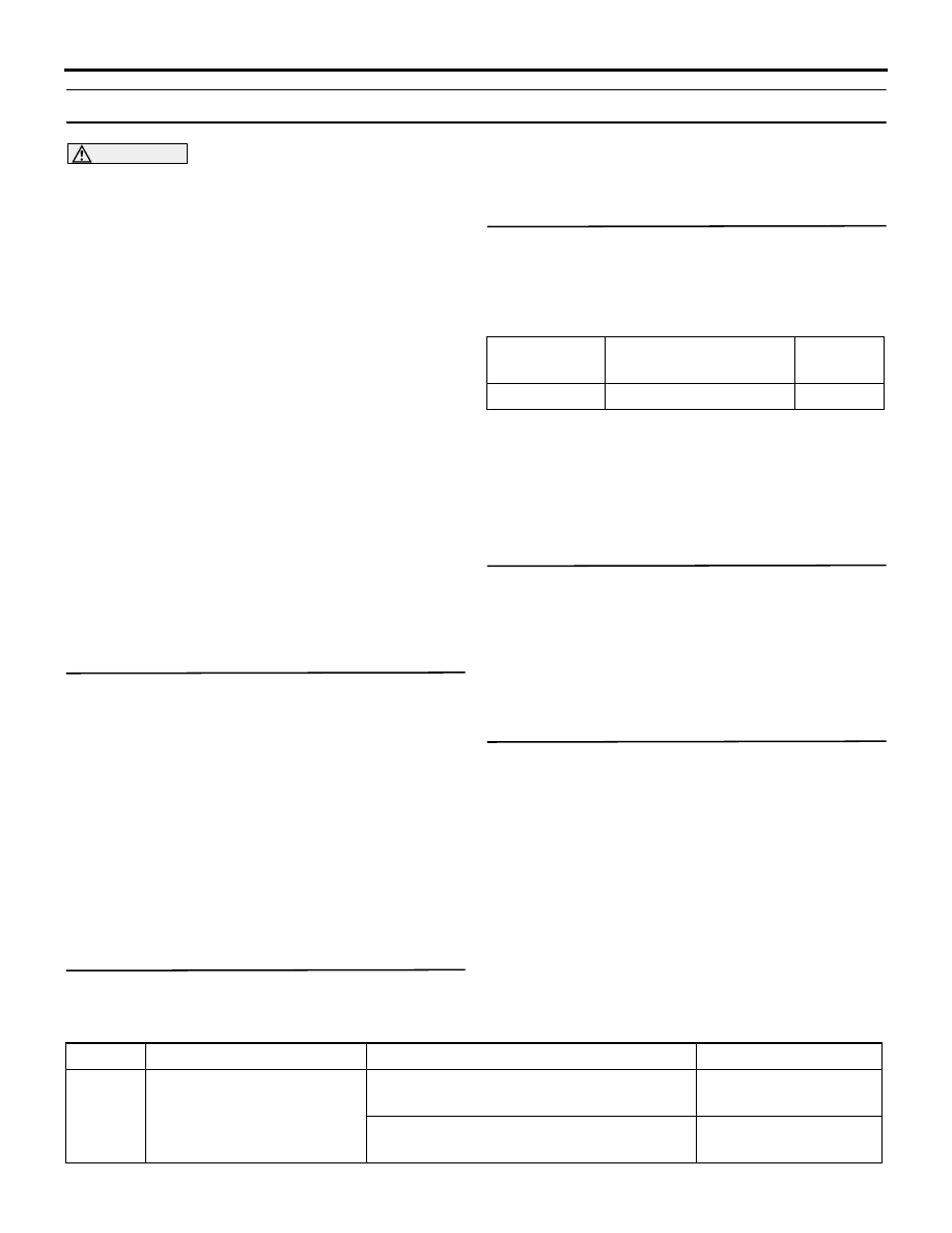
Item No.

Item name

Normal 
condition

Item 254

IG voltage

1 V or less

OK: Normal condition is displayed.

Q: Is the check result normal?

YES : 

Go to Step 4.

NO : 

Troubleshoot the ETACS-ECU. Refer to 
Inspection Procedure 2 "The ignition switch 
(IG1) signal is not received" 

P.54A-313

.

STEP 4. Check the headlamps.
When the lighting switch is operated, check that the 
headlamps illuminate/go off normally.

Q: Is the check result normal?

YES : 

Go to Step 5.

NO : 

Troubleshoot the headlamps. Refer to 
trouble symptom chart 

P.54A-96

.

STEP 5. Retest the system.
The coming home light function should work nor-
mally.

Q: Is the check result normal?

YES : 

The trouble can be an intermittent 

malfunction (Refer to GROUP 00 

− How to 

use Troubleshooting/inspection Service 
Points 

− How to Cope with Intermittent 

Malfunction ).

NO : 

Replace the ETACS-ECU.

DATA LIST REFERENCE TABLE

M1540103800508

Item No. M.U.T.-III display

Condition

Normal condition

7001

RLS IG1

When the ignition switch is turned to the 
LOCK or ACC position.

OFF

When the ignition switch is turned to the 
ON or START position.

ON

HEADLAMP

CHASSIS ELECTRICAL

54A-110

7002

RLS Light sensor sensitivity When the customise value of the lighting 

control sensor sensitivity is set to level 1 
(quick).

Level 1 bright

When the customise value of the lighting 
control sensor sensitivity is set to level 2 
(slightly quick).

Level 2 bright

When the customise value of the lighting 
control sensor sensitivity is set to level 3 
(normal).

Level 3

When the customise value of the lighting 
control sensor sensitivity is set to level 4 
(slightly slow).

Level 4 dark

When the customise value of the lighting 
control sensor sensitivity is set to level 5 
(slow).

Level 5 dark

7004

RLS Radio ACC

When the ignition switch is turned to the 
LOCK or START position.

OFF

When the ignition switch is turned to the 
ACC or ON position.

ON

7007

RLS Vehicle speed

Perform a test run of the vehicle.

The values displayed 
on the speedometer 
and M.U.T.-III are 
almost the same.

7009

RLS Low beam "ON" 
request

When the area around the lighting control 
sensor is bright.

OFF

When the area around the lighting control 
sensor is dark.

ON

7010

RLS judgement illuminance 
output

When the area around the lighting control 
sensor has become bright from dark

The value displayed on 
the M.U.T.-III becomes 
large.

When the area around the lighting control 
sensor has become dark from bright.

The value displayed on 
the M.U.T.-III becomes 
small.

7011

RLS Tail light "ON" request

When the area around the lighting control 
sensor is bright.

OFF

When the area around the lighting control 
sensor is dark.

ON

7012

RLS Tunnel detect output

When the area around the lighting control 
sensor is bright.

OFF

When the area around the lighting control 
sensor is dark.

ON

7014

RLS Specification

EU

7015

RLS ECU Diagnostic 
version

7016

RLS ECU Hardware 
version

Item No. M.U.T.-III display

Condition

Normal condition

HEADLAMP

CHASSIS ELECTRICAL

54A-111

ON-VEHICLE SERVICE

HEADLAMP AIMING

M1540100500650

<USING A BEAM SETTING EQUIPMENT>

AC102583

1. The headlamps should be aimed with the proper 

beam setting equipment, and in accordance with 
the equipment manufacture’s instructions.

2. Alternately turn the adjusting screw to adjust the 

headlamp aiming.

<USING A SCREEN> (LOW-BEAM) 

PRE-AIMING INSTRUCTION

1. Inspect for badly rusted or faulty headlamp 

assemblies.

2. These conditions must be corrected before a 

satisfactory adjustment can be made.

3. Inspect tyre inflation, and adjust if it is necessary.

4. If the fuel tank is not filled up, put weight in the 

luggage compartment to make up for the fuel 
shortage so that the weight will become 90% of 
full-state weight or heavier. (0.8 kg per litter)

5. There should be no other load in the vehicle other 

than driver or substituted weight of approximately 
75 kg placed in driver's position.

6. Turn the headlamp levelling switch to the switch 

position "0." <Vehicles with headlamp manual 
levelling system>

7. Change the vehicle posture, and then operate the 

actuator of headlamp levelling unit once. 
<Vehicles with headlamp automatic levelling 
system>

8. Thoroughly clean the headlamp lenses.

AC505906

(1)

(2)

(3)

(3)

AB

Vehicle centre line

Screen

Headlamp centre line

3 m

ACB05887

Bulb centre position

<Vehicles with halogen headlamp>

AB

ACB05888

<Vehicles with discharge headlamp>

Bulb centre position

AB

9. Place the vehicle on a level floor, perpendicular to 

a flat screen 3 m away from the bulb centre 
position of the low-beam.

10.Rock vehicle sideways to allow vehicle to assume 

its normal position.

11.To correct for distortion of the suspension, rock 

the bumpers on the front/rear side of the vehicle 
up and down three times alternately.

12.Run the engine at a speed of 2,000 r/min to 

charge the battery.

13.Four lines of adhesive tape (or equivalent 

markings) are required on screen or wall:
(1) Position a vertical tape or mark so that it is 

aligned with the vehicle centre line.

7017

RLS ECU Software version

7018

RLS ECU Part number

8634A001

7019

RLS ECU Serial number

Item No. M.U.T.-III display

Condition

Normal condition

HEADLAMP

CHASSIS ELECTRICAL

54A-112

(2) Measure the distance from the bulb centre 

position to the floor. Transfer the 
measurement to the screen. Horizontal tape or 
mark on the screen is for reference of vertical 
adjustment.

(3) Measure the distance from the centre line of 

the vehicle to the centre of each headlamp. 
Transfer the measurement to the screen. 
Vertical tape or mark on the screen with 
reference to the centre line of each headlamp 
bulb.

HEADLAMP ADJUSTMENT

CAUTION

Do not cover a headlamp for more than three 
minutes to prevent the plastic headlamp lens 
deformation.

1. The low-beam headlamp should project on the 

screen upper edge of the beam (cut-off).

CAUTION

Be sure to adjust the aiming adjustment screw in 
the tightening direction.

ACB05755

ACB05756AB

Vertical direction
adjusting screw

Horizontal direction
adjusting screw

Vertical direction

Phillips screwdriver

Horizontal direction

AC801142

Bulb centre position

(H)

AB

Elbow point

High intensity zone

Distance of 
vertical direction

(V)

2. If not the case, turn the adjusting screws to 

achieve the specified low-beam cut-off location on 
the aiming screen.

Standard value:
Vertical direction; 36 mm (0.69

°) below hori-

zontal (H)
Horizontal direction; Elbow point intersects 
the vertical line (V)

Limit:
Vertical direction; 

±15 mm (±0.29°) from the 

horizontal cut-off line


Content   ..  654  655  656  657   ..