Mitsubishi Outlander (2013+). Manual - part 647
 

  Index      Mitsubishi     Mitsubishi Outlander - service repair manual 2013 year


Search            


Content   ..  645  646  647  648   ..


Mitsubishi Outlander (2013+). Manual - part 647


COMBINATION METER

CHASSIS ELECTRICAL

54A-73

ON-VEHICLE SERVICE

SPEEDOMETER CHECK

M1540201400891

CAUTION

• Be sure to set the rear wheels on the free 

roller. (The vehicle may dash forward or the 
drive train may be damaged). <4WD>

• If the speedometer is checked using the 

speedometer tester, the diagnosis code may 
be stored in the ABS-ECU or ASC-ECU. 
Therefore, after the check is finished, erase 
the diagnosis code stored in the ABS-ECU or 
ASC-ECU.

• Do not accelerate or decelerate suddenly dur-

ing servicing work.

1. Check that the current tyre inflation pressures 

meet the inflation pressure label.

2. Press the ASC OFF switch for 3 seconds or more 

to stop the ASC operation <Vehicles with ASC>.

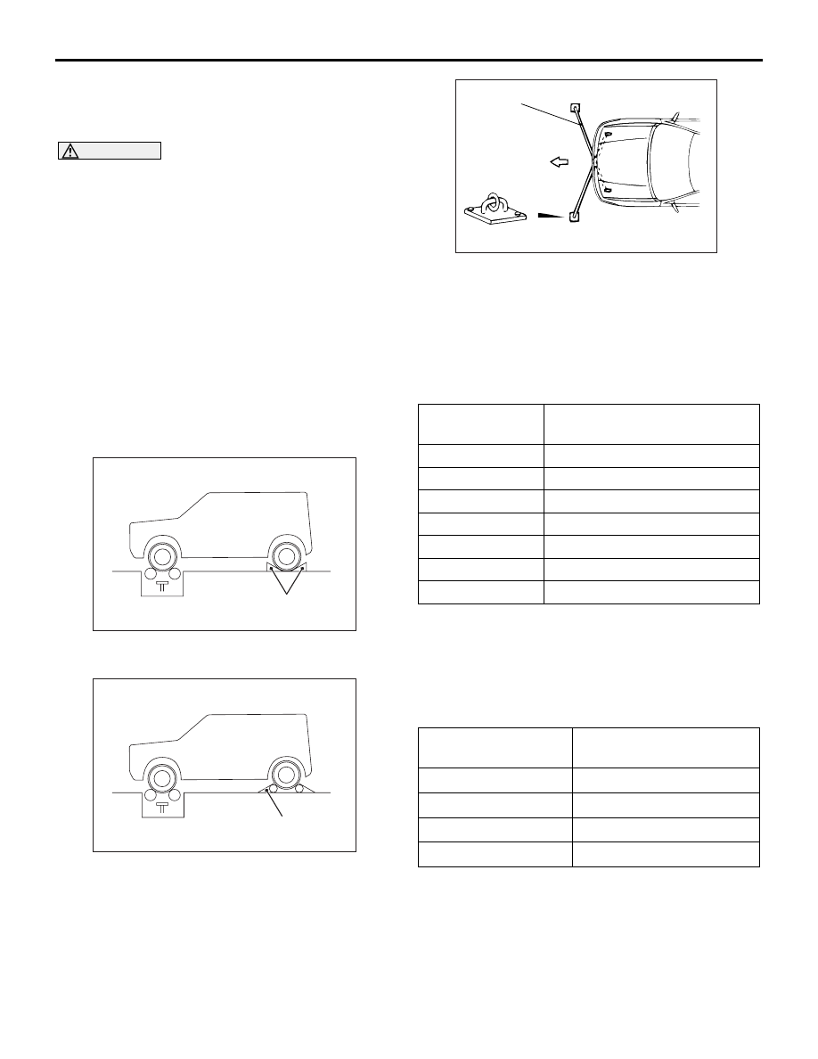
3. Set the vehicle on the speedometer tester.

AC802645 AB

<2WD>

Wheel chocks

Chock the rear wheels and apply the parking brake 

<2WD>.

AC802647 AB

<4WD>

Free roller

Place the rear wheels on the free roller. <4WD>

AC001288

Front

AC

Tension bar

Anchor plate

4. To prevent front wheel lateral runout or vehicle 

sudden start, attach a chain or wire to the front 
and rear towing hooks and fix the other end of the 
chain or wire to the anchor plate.

5. Check that the speedometer allowance range is 

within the standard value.

Standard value:

Standard 
indicator km/h

Allowance range km/h

20

20.25 

− 22.25

40

40.5 

− 44.5

80

81.5 

− 86.5

120

122.5 

− 128.5

160

162.5 

− 169.5

200

202.5 

− 210.5

240

242.5 

− 251.5

TACHOMETER CHECK

M1540201500542

When the actuator tests (item No. 2) are performed 
using M.U.T.-III, check that the tachometer indication 
tolerance is within the standard value.

Standard value:

Engine speed r/min

Tachometer indicating 
tolerance r/min

600

± 100

3,000

± 100

5,000

± 100

6,000

± 100

COMBINATION METER

CHASSIS ELECTRICAL

54A-74

FUEL GAUGE UNIT CHECK

M1540201600903

<2WD>

NOMINAL RESISTANCE OF THE FUEL 
GAUGE UNIT

1. Remove the fuel pump and gauge assembly 

(Refer to GROUP 13B 

− On-vehicle Service, Fuel 

Pump and Gauge Assembly Replacement ).

ACC00436

Earth

Fuel gauge unit

F

E

AB

2. When float of the fuel gauge unit is in stopper 

positions "F" and "E", ensure that resistance 
between the fuel gauge unit terminal and earth 
terminal is within the standard value.

Standard value:

Float position

Gauge resistance value 

Stopper position "F" 13.0 

± 1.0

Stopper position "E" 120.0 

± 1.0

3. When the float is moved slowly between stopper 

positions "F" and "E", ensure that the resistance is 
smoothly changing.

FUEL GAUGE UNIT FLOAT HEIGHT

1. Remove the fuel pump and gauge assembly 

(Refer to GROUP 13B 

− On-vehicle Service, Fuel 

Pump and Gauge Assembly Replacement ).

ACC00437

F

AB

A

E

B

2. When float is moved to contact the float arm on 

the stopper, ensure that stopper positions "F" and 
"E" are within the standard value.

Standard value:

Float position

Float height mm

Stopper position "F" 
(height A)

201.6

Stopper position "E" 
(height B)

18.0

<4WD>

NOMINAL RESISTANCE OF THE FUEL 
GAUGE UNIT

1. Remove the fuel pump and gauge assembly 

(Refer to GROUP 13B 

− On-vehicle Service, Fuel 

Pump and Gauge Assembly Replacement ) 
<Main>.

2. Remove the fuel gauge unit (Refer to GROUP 

13B 

− On-vehicle Service, Fuel Gauge Unit 

Replacement ) <Sub>.

ACC00438

Earth

Fuel gauge unit

Earth

Fuel gauge unit

F

E

F

E

AB

<Main>

<Sub>

COMBINATION METER

CHASSIS ELECTRICAL

54A-75

3. When float of the fuel gauge unit is in stopper 

positions "F" and "E", ensure that resistance 
between the fuel gauge unit terminal and earth 
terminal is within the standard value.

Standard value:

Float position

Gauge resistance value 

Main

Sub

Stopper position 
"F"

6.5 

± 1.0

6.5 

± 1.0

Stopper position 
"E"

44.7 

± 1.0

75.3 

± 1.0

4. When the float is moved slowly between stopper 

positions "F" and "E", ensure that the resistance is 
smoothly changing.

FUEL GAUGE UNIT FLOAT HEIGHT

1. Remove the fuel pump and gauge assembly 

(Refer to GROUP 13B 

− On-vehicle Service, Fuel 

Pump and Gauge Assembly Replacement ) 
<Main>.

2. Remove the fuel gauge unit (Refer to GROUP 

13B 

− On-vehicle Service, Fuel Gauge Unit 

Replacement ) <Sub>.

ACC00439

F

F

E

AB

A

B

E

A

B

<Main>

<Sub>

3. When float is moved to contact the float arm on 

the stopper, ensure that stopper positions "F" and 
"E" are within the standard value.

Standard value:

Float position

Float height mm

Main

Sub

Stopper position "F" 
(height A)

166.2

48.8 

± 3.0

Stopper position "E" 
(height B)

38.8

238.0 

± 3.0

COMBINATION METER

CHASSIS ELECTRICAL

54A-76

SERVICE REMINDER FUNCTION SET

M1540208200724

HOW TO SET BY OPERATING M.U.T.-III

CAUTION

• If the combination meter needs to be 

replaced, the current driving distance and 
elapsed days must be entered into the meter 
after the replacement in order to be used for 
service reminder function. Therefore, read 
"Integrated mileage for reminder," "Integrated 
days for reminder," "Mileage until Extra 
reminder," "Months until Extra reminder," and 
"Current schedule" from the meter before the 
replacement using the special function of 
M.U.T.-III, and note them. If "Integrated mile-
age for reminder" or "Integrated days for 
reminder" cannot be read from the meter 
using M.U.T.-III, use the following method.

a. As for the driving distance for check warn-

ing, use the driving distance displayed on 
the odometer.

b. As for the elapsed days for check warning, 

calculate the number of elapsed days from 
the delivery date to the customer (service 
reminder function start date) and current 
date.

• After the service reminder function has 

started, when the elapsed days for check 
warning is reset for the vehicle whose battery 
is removed for a long period (15 days or 
more), calculate the elapsed days from the 
delivery date to the customer (service 
reminder function start date) and the current 
date, and then input it.

Using M.U.T.-III, the following service reminder func-
tions can be set. Before setting, check the current 
status (schedule, elapsed distance and elapsed 
days).

1. Extra reminder setting
2. Extra reminder cancel
3. Periodic reminder schedule set 
4. Integrated value adjustment
5. Optional INT schedule setting

HOW TO OPERATE M.U.T.-III

CAUTION

Before setting the service reminder, if elapsed 
days are not calculated, turn the ignition switch 
to the OFF position. Then press the meter infor-
mation switch. Then, press the meter information 
switch for 1.2 second or more to make the serv-
ice reminder indicator flash. While the service 
reminder indicator is flashing, press the meter 
information switch for 1.2 second or more to 
start the measurement.
1. Connect M.U.T.-III to the diagnosis connector (16 

pin).

2. Start the M.U.T.-III system on the PC and turn the 

ignition switch to the "ON" position.

3. Select "Meter" on the "System Select" screen, 

and press the "OK" button.

4. Select "Special Function" on the next screen.

5. Select "Service Reminder" on the "Special 

function" screen.

AC602555

DBA-CW5WXTHHZ1 2006MY - Service Reminder - 401430898

Meter

Special Function

Function List

Mileage until reminder

15000 km

12 month

EU 1

26 km

Months until reminder

Current Schedule

Integrated mileage 
for reminder

Mileage until Extra 
reminder

Months until Extra 
reminder

Extra reminder setting

Extra reminder cancel

Periodic reminder schedule set

Integrated value adjustment

Optional INT schedule setting

Click the name of item to execute, and press 
the OK button.

Name

No.

3

4

1

2

5

6

7

4

5

7

8

Name

Value

No.

Service Reminder

Data List

AO

6. Select the function to be executed from "Function 

List."

• 3 Extra reminder setting (Refer to 

P.54A-76

.)

• 4 Extra reminder cancel (Refer to 

P.54A-77

.)

• 5 Periodic reminder schedule set (Refer to 

P.54A-77

.)

• 6 Integrated value adjustment (Refer to 

P.54A-78

.)

• 7 Optional INT schedule setting (Refer to 

P.54A-79

.)

1. EXTRA REMINDER SETTING

In addition to the current warning period, the tempo-
rary service reminder warning period can be set.

NOTE: Prior to this Extra reminder setting, execute 
the Extra reminder cancel and the Periodic reminder 
schedule set (including the case that it is not neces-
sary to change the schedule).


Content   ..  645  646  647  648   ..