Mitsubishi Outlander (2013+). Manual - part 600
TROUBLESHOOTING
SUPPLEMENTAL RESTRAINT SYSTEM (SRS)
52B-51
STEP 4. Check of short to power supply, short to
earth, and open circuit in SSR-, SSR+ line in
between SRS-ECU connector and side impact
sensor (RH) connector.
Q: Is the check result normal?
YES :
Go to Step 5
NO :
Repair the connectors or harness wires.
STEP 5. Check whether the diagnosis code is
reset.
Q: Is the diagnosis code B1428 or B1429 set?
YES :
Replace SRS-ECU (Refer to
NO :
Intermittent malfunction (Refer to GROUP
00
− How to Use
Troubleshooting/Inspection Service Points
−
How to Cope with Intermittent Malfunction ).
Code No.B1430 Left side-airbag module (squib) system (short circuit between squib terminals)
CAUTION
If the diagnosis code B1430 is set to SRS-ECU,
be sure to diagnose the CAN bus line.
OPERATION
In case of side collision, when the impact exceeding
the threshold is applied to the vehicle, and when the
impact is simultaneously detected (turned ON) by the
side impact sensor as well as by the analogue
G-sensor in SRS-ECU, the electric current is sup-
plied from SRS-ECU to the side-airbag module
(squib) of impacted side.
TROUBLE JUDGEMENT
The code is set when the short circuit occurs to
between the terminals of SRS-ECU side-airbag mod-
ule (squib) circuit.
PROBABLE CAUSES
• Damaged short spring
*
• Short circuit between terminals of side-airbag
module (squib) circuit
• Damaged connector(s)
• Malfunction of SRS-ECU
NOTE: *: The squib circuit connectors integrate a
short spring (which prevents the air bags from being
unintentionally deployed because of static electricity
by shorting the positive wire to the earth wire in the
squib circuit when the connectors are disconnected).
Therefore, when the above codes are set, the short
spring may not be released due to the damaged con-
nector even when the connectors are connected.
DIAGNOSIS PROCEDURE
STEP 1. M.U.T.-III CAN bus diagnostics.
Use M.U.T.-III to diagnose the CAN bus lines.
Q: Is the check result normal?
YES :
Go to Step 2.
NO :
Repair the CAN bus line (Refer to GROUP
54C
− Troubleshooting ).
STEP 2. Check whether the diagnosis code is
reset.
(1) Connect the negative battery terminal.
(2) After erasing the diagnosis code memory, check
the diagnosis code again.
(3) Disconnect the negative battery terminal.
Q: Is the diagnosis code No. B1430 set?
YES :
Go to Step 3.
NO :
Intermittent malfunction (Refer to GROUP
00
− How to Use
Troubleshooting/Inspection Service Points
−
How to Cope with Intermittent Malfunction ).
STEP 3. Connector check: SRS-ECU, left
side-airbag module.
(1) Check that the negative battery terminal is
disconnected. If the negative battery terminal is
connected, disconnect it.
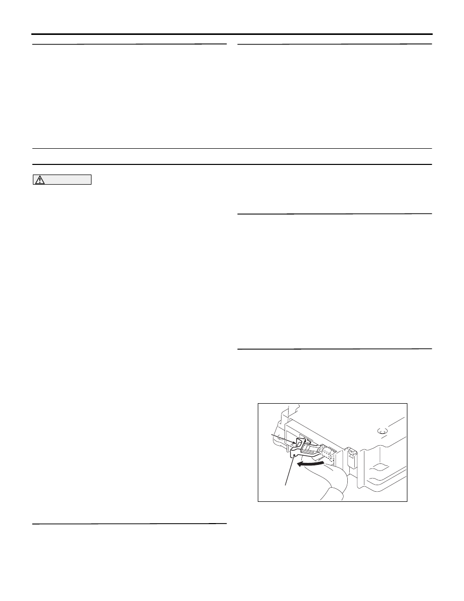
AC905015
A
AC
Lock lever
(2) While pushing the part "A" indicated in the figure
of the harness side connector, turn the lock lever
to the direction of the arrow to release the lock
lever. After disconnecting the SRS-ECU