Mitsubishi Outlander (2013+). Manual - part 438
 

  Index      Mitsubishi     Mitsubishi Outlander - service repair manual 2013 year


Search            


Content   ..  436  437  438  439   ..


Mitsubishi Outlander (2013+). Manual - part 438


FRONT DISC BRAKE ASSEMBLY

BASIC BRAKE

35A-19

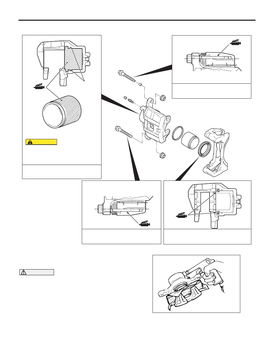
LUBRICATION POINTS

AC607854

AE

Brake fluid: DOT 3 or DOT 4

Grease: Repair kit grease, Niglube RX-2 
              or equivalent

The piston seal inside the caliper seal
kit is coated with a special grease.
Do not wipe this grease off. 

CAUTION

Piston seal

Grease: Repair kit grease, Niglube RX-2 
              or equivalent

Grease: Repair kit grease, Niglube RX-2 
              or equivalent

DISASSEMBLY SERVICE POINTS

<<A>> PISTON/PISTON BOOT REMOVAL

CAUTION

Blow air gradually to remove the pistons. The 
pistons will rush out if a force of air is applied 
suddenly.

ACX00697

Cover the caliper body outer side with a cloth or sim-
ilar materials. Blow compressed air through the 
brake hose installation area to remove the piston and 
piston boot.

FRONT DISC BRAKE ASSEMBLY

BASIC BRAKE

35A-20

<<B>> PISTON SEAL REMOVAL

CAUTION

Do not use a flat-tipped screwdriver to remove 
the piston seal. This may damage the inner side 
of the cylinder.

ACX00689

1. Remove the piston seal with your finger tip.

2. Clean the piston surface and cylinder inner face 

with alcohol or specified brake fluid.

Brake fluid: DOT3 or DOT4

INSPECTION

M1351015001099

BRAKE PAD WEAR INSPECTION

CAUTION

• When replacing, replace both brake pad 

assembly (right and left) as a set.

ACC00790

If there is a significant difference in thickness 
between the brake pads at right and left, 
check the sliding area of the brake caliper.

Measure the brake pad thickness at the most worn 
area. If the brake pad thickness is less than the limit 
value, replace the brake pad.

Standard value: 10.0 mm
Limit: 2.0 mm

REAR DISC BRAKE ASSEMBLY

BASIC BRAKE

35A-21

REAR DISC BRAKE ASSEMBLY

REMOVAL AND INSTALLATION

M1351007001544

Pre-removal operation
Brake Fluid Draining

Post-installation operation
• Brake Fluid Supplying and Air Bleeding (Refer to 

P.35A-7

).

• Parking Brake Lining Seating Procedure (Refer to 

GROUP 36 

− On-vehicle Service, Parking Brake Lining 

Seating Procedure ).

ACC00169AB

1

3

4

2

5

30 ± 5 N·m

2

7

6

13 ± 2 N·m

9

8

11 ± 2 N·m

11 ± 2 N·m

10

58 ± 7 N·m

N

N

16 ± 3 N·m

16 ± 3 N·m

16 ± 3 N·m

Removal steps 

Parking brake rear cable 
connection (rear brake caliper side) 
(Refer to GROUP 36 

− Parking 

Brake Cable ).

1.

Brake hose connection bolt

2.

Gasket

>>A<<

3.

Brake hose (rear brake caliper 
side)

4.

Rear brake caliper assembly

Brake disc run-out check and 
correction (only at installation) 
(Refer to 

P.35A-9

).

5.

Rear brake disc

6.

Hose clip

7.

bracket

8.

Brake tube (trailing arm side)

9.

Clip

10. Brake tube (body floor side)

INSTALLATION SERVICE POINT

>>A<< BRAKE HOSE INSTALLATION

1. Pass the brake hose through the hole in the 

bracket.

2. Install the brake hose to the brake caliper.

3. Install the brake hose at the two fixing points. 

AC507195

A

View A

Correct

Bracket

Brake hose

AB

Wrong

REAR DISC BRAKE ASSEMBLY

BASIC BRAKE

35A-22

4. Twist the brake hose toward the lesser torsion 

between the brake hose and bracket as shown in 
the figure, and fix it to the body-side bracket with a 
clip.

DISASSEMBLY AND REASSEMBLY

M1351007201678

ACB06044

<Right side>

<Left side>

Rear brake pad set

Repair kit grease

Rear brake caliper kit

Repair kit grease

Rear brake clip set

Seal & boot kit

Shim kit

AB

3

3

3

5

5

5

5

4

4

6

7

9

10

11

8

6

2

1

35 ± 4 N·m

1

35 ± 4 N·m

12

8

14

7.9 ± 0.9 N·m

13

2

9

11

10

8

8

7

6

1

12

1

6

13

14

8

11

8

10

4

4

4

4

7

<Left side>

<Right side>

<Right side>

<Left side>

15

15

N

N

N

N

Repair kit grease

Repair kit grease


Content   ..  436  437  438  439   ..