Mitsubishi Outlander (2013+). Manual - part 425
 

  Index      Mitsubishi     Mitsubishi Outlander - service repair manual 2013 year


Search            


Content   ..  423  424  425  426   ..


Mitsubishi Outlander (2013+). Manual - part 425


SERVICE SPECIFICATIONS

FRONT SUSPENSION

33-2

SERVICE SPECIFICATIONS

M1332000302195

Item

Standard value

Toe-in 

At the centre of tyre tread mm

± 2

Toe-in angle (per wheel)

0

°02' ± 0°04'

Camber

0

°20' ± 0°30'

*

Caster

2

°35' ± 0°45'

*

Kingpin inclination

12

°45' ± 1°30'

Lower arm ball joint rotation starting torque N

⋅m

0.3 

− 9.0

Stabilizer link ball joint rotation torque N

⋅m

0.3 

− 2.9

NOTE: *: Difference between right and left wheels must be 0

°

30' or less.

LUBRICANT

M1332000400389

Item

Specified Lubricant

Quantity

Inside and lip of lower arm ball 
joint dust cover

Multipurpose grease SAE J310, 
NLGI No.2 or equivalent

Inside of dust cover : 9.0 

± 1.0 g

Lip: As required

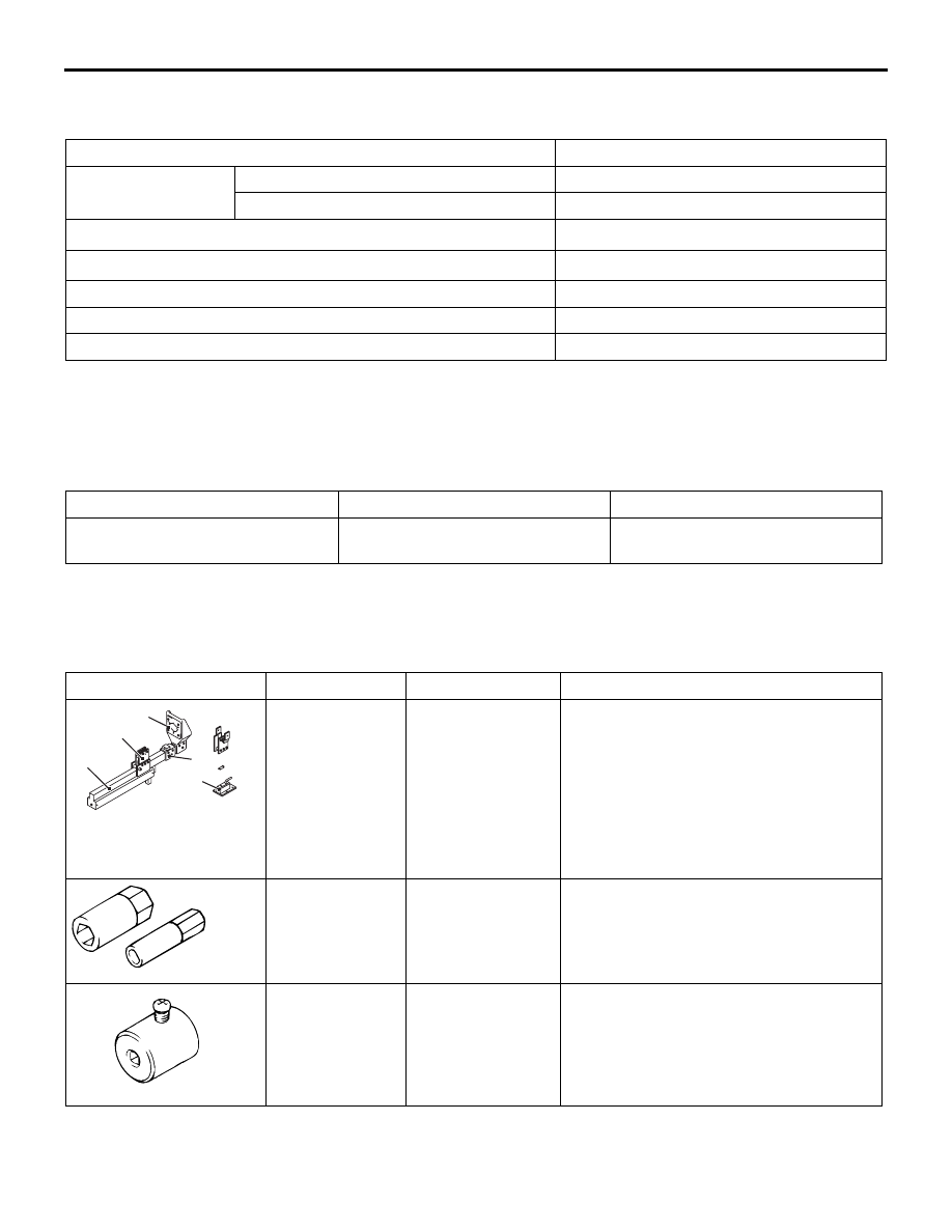
SPECIAL TOOLS

M1332000601193

Tool

Number

Name

Use

MB991832

a

b

e

c

d

MB991832

a. MB991793
b. MB991795
c. MB991794
d. MB991829
e. MB991830

Spring compressor 
set

a. Spring 

compressor

b. Attachment A
c. Upper plate
d. Arm bracket
e. Fixture

Coil spring compression

MB991680

A

B

A

B

a

b

MB991680

a. MB991681
b. MB991682

Wrench set

a. Wrench
b. Socket

Strut assembly disassembly and 
assembly

MB991006

MB991006

Preload socket

Lower arm ball joint rotation starting 
torque measurement

MB990800

SPECIAL TOOLS

FRONT SUSPENSION

33-3

MB990800

Ball joint remover 
& installer

Lower arm ball joint dust cover press-fit

MB992119

MB992119

Arm bushing 
remover

Lower arm bushing removal

MB990979

Ring

MB990890

MB990890

Rear suspension 
bushing base

MD998375

Arm bushing 
installer

Lower arm bushing press-fit

MB992868

Spacer base

MB990643

MB990643

Rear suspension 
bushing base

MB990326

MB990326

Preload socket

Stabilizer link ball joint rotation torque 
measurement

Tool

Number

Name

Use

ON-VEHICLE SERVICE

FRONT SUSPENSION

33-4

ON-VEHICLE SERVICE

FRONT WHEEL ALIGNMENT CHECK AND 
ADJUSTMENT

M1332012400621

CAUTION

Perform a calibration for the ASC-ECU to learn 
the steering wheel sensor neutral point (Refer to 
GROUP 35C, On-vehicle Service 

 Steering 

Wheel Sensor Calibration ) <Vehicles with ASC>.

• Before the wheel alignment measurement, main-

tain the front suspension, the steering system 
and the wheel tyres in good condition.

• Park the vehicle on a level surface, and position 

the front wheel in the straight- ahead position to 
measure the wheel alignment.

TOE-IN

Standard value:

At the centre of tyre tread: 1 

± 2 mm

Toe-angle (per wheel): 0

°02' ± 0°04'

AC506665AB

Bellows
clip

Lock nut

1. Loosen the lock nut with tie-rod bellows clip 

removed, and then perform the adjustment by 
turning the tie-rod left/right at the same degree in 
the opposite direction.

NOTE: The toe moves to the outside by turning 
the tie-rod: left to the forward direction, and right 
to the reverse direction.

2. After adjustment, check that the steering angle is 

within the standard range using the turning radial 
gauge (GROUP 37 

− On-vehicle Service, Steering 

Angle Check ).

CAMBER

CASTER AND KINGPIN INCLI-

NATION

CAMBER

Standard value: 0

°20' ± 0°30'

CASTER

Standard value: 2

°35' ± 0°45'

NOTE: 

.

Difference between right and left wheels must be 
0

°

30' or less.

The camber and the caster are pre-adjusted at 
factory and not adjustable.

KINGPIN INCLINATION

Standard value: 12

°45' ± 1°30'

CAUTION

Do not apply the vehicle weight to the wheel 
bearing while loosening the driveshaft nut.

NOTE: 

.

The camber is pre-adjusted at factory and is not 
adjustable.

AC102503

Compensator

AD

As for vehicles with aluminium wheel, use a compen-

sator to measure the camber and caster.

LOWER ARM BALL JOINT LOOSENESS 
CHECK

M1332015000387

1. Raise the vehicle.

2. Move the lower arm vertically to inspect the ball 

joint for looseness in the axial direction. If there is 
looseness, replace the lower arm assembly 
(Refer to

P.33-10

).

BALL JOINT DUST COVER CHECK

M1332013200181

LOWER ARM BALL JOINT DUST COVER 
CHECK

1. Using your fingers, press the dust cover to check 

for a crack or damage.

2. If the dust cover has any crack or damage, 

replace the lower arm assembly (Refer to 

P.33-10

).

NOTE: If the dust cover has a crack or damage, 
the ball joint could be damaged.

STRUT ASSEMBLY

FRONT SUSPENSION

33-5

STABILIZER LINK BALL JOINT DUST 
COVER CHECK

1. Check the dust cover for cracks or damage by 

pushing it with your finger.

2. If the dust cover is cracked or damaged, replace 

the stabilizer link (Refer to 

P.33-13

).

NOTE: If the dust cover has a crack or damage, 
the ball joint could be damage.

STRUT ASSEMBLY

REMOVAL AND INSTALLATION

M1332001101599

CAUTION

• The part indicated by 

*

 is the nut with friction coefficient stabilizer. In removal, ensure there is no 

damage, clean dust and soiling from the bearing and thread surfaces, and tighten it to the speci-
fied torque.

Pre-removal Operation
• Front Height Sensor Removal (Refer to GROUP 54A − 

Height Sensor ). <Vehicles with discharge headlamp>

Post-installation Operation
• Front Height Sensor Installation (Refer to GROUP 54A − 

Height Sensor ). <Vehicles with discharge headlamp>

• Front Wheel Alignment Check and Adjustment (Refer to 

P.33-4

).

ACB05446

AB

6

3

2

39 ± 6 N·m

45 ± 7 N·m

110 ± 11 N·m

13 ± 2 N·m

5

1

9.5 ± 2.5 N·m

*1

*2

<Right side>

Front height 
sensor

Stabilizer link

5


Content   ..  423  424  425  426   ..