Mitsubishi Outlander (2013+). Manual - part 344
 

  Index      Mitsubishi     Mitsubishi Outlander - service repair manual 2013 year


Search            


Content   ..  342  343  344  345   ..


Mitsubishi Outlander (2013+). Manual - part 344


CHARGING SYSTEM

ENGINE ELECTRICAL

16-12

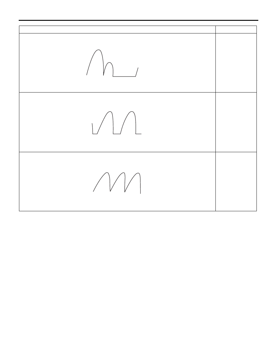
Example 2 

AKX00192

Short in diode

Example 3 

AKX00193

Broken wire in 
stator coil

Example 4 

AKX00194

Short in stator 
coil

Abnormal waveform

Problem cause

CHARGING SYSTEM

ENGINE ELECTRICAL

16-13

ALTERNATOR ASSEMBLY

REMOVAL AND INSTALLATION

M1161001403912

Pre-removal operation
• Drive Belt Removal (Refer to GROUP 11A − Crankshaft 

Pulley ).

Post-installation operation
• Drive Belt Installation (Refer to GROUP 11A − Crankshaft 

Pulley ).

• Drive Belt Tension Check (Refer to GROUP 11A − 

On-vehicle Service, Drive Belt Tension Check ).

ACC00077

1

2

3

5

4

6

7

12 ± 2 N·m

44 ± 10 N·m

23 ± 6 N·m

44 ± 8 N·m

AB

44 ± 10 N·m

Removal steps 

1.

Idler pulley

2.

A/C compressor and clutch 
assembly connector

<<

A

>>

>>

C

<<

3.

A/C compressor and clutch 
assembly

4.

Alternator connector

5.

Alternator terminal

>>

B

<<

6.

Earth cable connection

<<

B

>>

>>

A

<<

7.

Alternator assembly

REMOVAL SERVICE POINTS

<<A>> A/C COMPRESSOR AND CLUTCH 
ASSEMBLY REMOVAL

1. Remove the A/C compressor and clutch assembly 

together with the hose from the bracket.

2. Tie the removed A/C compressor and clutch 

assembly with a string at a position where they 
will not interfere with the removal and installation 
of the alternator assembly.

<<B>> ALTERNATOR ASSEMBLY 
REMOVAL

Remove the alternator assembly to the downside.

INSTALLATION SERVICE POINTS

>>A<< ALTERNATOR ASSEMBLY 
INSTALLATION

1. Install the alternator to the accessory bracket.

2. Tighten the bolt on the upper side to the specified 

torque.

Tightening torque: 44 

± 10 Nm

3. Tighten the nut on the lower side to the specified 

torque.

Tightening torque: 44 

± 10 Nm

>>B<< EARTH CABLE CONNECTION

ACB05845 AB

A

Earth cable 
terminal

CHARGING SYSTEM

ENGINE ELECTRICAL

16-14

Install the earth cable within the area marked with A 
in the illustration.

>>C<< A/C COMPRESSOR AND CLUTCH 
ASSEMBLY INSTALLATION

AC506759

AC

1

2

3

A/C compressor 
and clutch assembly

Tighten A/C compressor and clutch assembly mount-
ing bolts to the specified torque in the order of 
number shown in the illustration.

Tightening torque: 23 

± 6 Nm

DISASSEMBLY AND REASSEMBLY

M1161001601073

AKC00022

3

4

5

6

7

8

9

10

11

12

13

14

15

AB

118 ± 20 N·m

2

3.9 ± 1.0 N·m

4.4 ± 1.0 N·m

3.9 ± 1.0 N·m

16 ± 2 N·m

1

Disassembly steps 

<<

A

>>

1. Front bracket assembly

<<

B

>>

2. Alternator pulley
3. Rotor
4. Rear bearing
5. Bearing retainer
6. Front bearing

>>

B

<< 7. Front bracket

<<

C

>>

8. Stator
9. Plate

<<

C

>> >>

A

<< 10. Regulator assembly

11. Brush
12. Rubber packing
13. Rectifier
14. Insulator
15. Rear bracket

CHARGING SYSTEM

ENGINE ELECTRICAL

16-15

DISASSEMBLY SERVICE POINTS

<<A>> FRONT BRACKET REMOVAL

AK703439

CAUTION

Do not insert the screwdriver blades too deep. 
Doing so could damage the stator coil.
Insert the blades of screwdrivers between the front 
bracket and stator core, and pry and separate them 
with the screwdrivers.

<<B>> ALTERNATOR PULLEY REMOVAL

AK400387

CAUTION

Perform operation carefully not to damage the 
rotor.
Clamp the rotor in a vise with the pulley facing up to 
remove the pulley.

<<C>> STATOR / REGULATOR HOLDER 
REMOVAL

AK602877

Solder

Solder

Rectifier 
assembly

AB

CAUTION

• Use care that no undue force is exerted to 

lads of diodes.

• Check that the heat from the soldering iron is 

not transmitted to the diode for a long time.

1. Use a soldering iron (180 to 250 W) to unsolder 

the stator. This work should complete within 
approximately four seconds to prevent heat from 
transferring to the diode.

2. When removing the rectifier from the regulator 

assembly, unsoldered on the rectifier.

REASSEMBLY SERVICE POINTS

>>A<< REGULATOR ASSEMBLY INSTAL-
LATION

AK802863

Wire

AD

After installing the regulator assembly, insert a piece 
of wire through the hole in the rear bracket while 
pressing the brush to keep the brush against move-
ment.

NOTE: Unless inserting the wire to fix the brush, the 
rotor installation is difficult.


Content   ..  342  343  344  345   ..