Mitsubishi Outlander (2013+). Manual - part 337
 

  Index      Mitsubishi     Mitsubishi Outlander - service repair manual 2013 year


Search            


Content   ..  335  336  337  338   ..


Mitsubishi Outlander (2013+). Manual - part 337


AC302615

Hose clip

Claw (Tip)

AE

THERMOSTAT

ENGINE COOLING

14-14

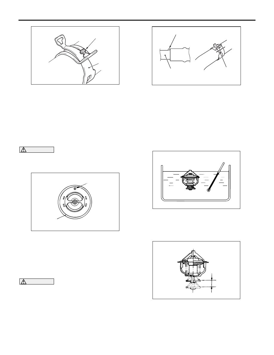
2. Break off the tip of hose clip claw and spread out 

the hose clip, then disconnect the radiator lower 
hose.

NOTE: If there is a hose clip claw, the hose clip 
cannot spread to capacity because the claw con-
tacts the hose clip.

INSTALLATION SERVICE POINTS

>>A<< THERMOSTAT INSTALLATION

CAUTION

Avoid adhesion of grease to the rubber ring of 
the thermostat. If the rubber ring is damaged, 
replace the thermostat.

AC005977AB

Rubber ring

Jiggle valve

Install the thermostat with care to avoid peeling or 
damage to the rubber ring. When installing the ther-
mostat, face the jiggle valve of the thermostat 
upward.

>>B<< RADIATOR LOWER HOSE/HOSE 
CLIP CONNECTION

CAUTION

Never reuse the hose clip whose claw is broken 
off to prevent the rusting.

1. Make mating mark on a new hose clip in the same 

position as the remove one.

AC606082

Protrusion

Water inlet fitting

AW

Mating marks

2. Insert the radiator lower hose until the protrusion 

of the water inlet fitting.

3. Align the mating marks on the radiator lower hose 

and hose clip.

4. Remove the hose clip claw and shorten the hose 

clip, then install the radiator lower hose.

INSPECTION

M1141002501969

THERMOSTAT CHECK

ACX00400AB

1. Immerse the thermostat in water, and heat the 

water while stirring. Check the thermostat valve 
opening temperature.

Standard value: 82 

± 1.5°

ACX00401AC

Valve lift

2. Check that the amount of valve lift is at the 

standard value when the water is at the 
full-opening temperature.

WATER PUMP

ENGINE COOLING

14-15

NOTE: Measure the valve height when the ther-
mostat is fully closed, and use this measurement 
to compare the valve height when the thermostat 
is fully open.

Standard value:

Full-opening temperature: 95

°C

Amount of valve lift: 8.5 mm or more

WATER PUMP

REMOVAL AND INSTALLATION

M1141002702999

Pre-removal Operation
• Engine Coolant Draining (Refer to 

P.14-9

).

• Alternator and Others Belt Removal (Refer to GROUP 

11A 

− Crankshaft Pulley ) .

Post-installation Operation
• Alternator and Others Belt Installation (Refer to GROUP 

11A 

− Crankshaft Pulley ) .

• Alternator and Others Belt Tension Check (Refer to 

GROUP 11A 

− On-vehicle Service, Drive Belt Tension 

Check and Adjustment ) .

• Engine Coolant Refilling (Refer to 

P.14-9

).

AC509330

24 ± 3 N·m

24 ± 3 N·m

24 ± 3 N·m

2

1

4

5

N

N

AB

9.0 ± 1.0 N·m

3

Removal steps 

1.

Water pump pulley

2.

Water pump inlet pipe mounting 
nuts

3.

Water pump

4.

Cooling water line gasket

5.

Water pump gasket

Removal steps (Continued)

WATER HOSE AND WATER PIPE

ENGINE COOLING

14-16

WATER HOSE AND WATER PIPE

REMOVAL AND INSTALLATION

M1141003304268

Pre-removal Operation
• Engine Coolant Draining (Refer to 

P.14-9

).

• Engine Upper Cover Removal (Refer to GROUP 11A − 

Camshaft ) .

• Air Cleaner Assembly Removal (Refer to GROUP 15 − Air 

Cleaner ) .

• Thermostat Removal (Refer to 

P.14-13

).

Post-installation Operation
• Thermostat Installation (Refer to 

P.14-13

).

• Air Cleaner Assembly Installation (Refer to GROUP 15 − 

Air Cleaner ) .

• Engine Upper Cover Installation (Refer to GROUP 11A − 

Camshaft ) .

• Engine Coolant Refilling (Refer to 

P.14-9

).

ACB04946

1

3

4

5

6

7

8

9

10

12

13

14

15

16

17

11 ± 1 N·m

30 ± 9 N·m

10 ± 2 N·m

5.0 ± 1.0 N·m

N

N

N

N

AB

24 ± 3 N·m

24 ± 3 N·m

24 ± 3 N·m

24 ± 3 N·m

18

11 ± 1 N·m

2

N

11

Removal steps 

1.

Vacuum pipe assembly

<<

A

>>

>>

C

<<

2.

Hose clip

<<

A

>>

>>

C

<<

3.

Radiator upper hose connection

4.

Throttle body water feed hose

5.

Water outlet fitting

6.

Water outlet fitting gasket

7.

Engine coolant temperature 
sensor connector

8.

Control wiring harness 
connection

<<

B

>>

>>

B

<<

9.

Engine coolant temperature 
sensor

10. Earth cable connection
11. Throttle body water return hose
12. Wiring harness bracket
13. Heater hose connection
14. Thermostat case

Removal steps (Continued)

WATER HOSE AND WATER PIPE

ENGINE COOLING

14-17

REMOVAL SERVICE POINTS

<<A>> HOSE CLIP/RADIATOR UPPER 
HOSE DISCONNECTION

AC606081

Mating marks

AE

1. Make mating marks on the radiator upper hose 

and the hose clip as shown to install them in the 
original position.

AC302615

Hose clip

Claw (Tip)

AE

2. Break off the tip of hose clip claw and spread out 

the hose clip, then disconnect the radiator upper 
hose.

NOTE: If there is a hose clip claw, the hose clip 
cannot spread to capacity because the claw con-
tacts the hose clip.

<<B>> ENGINE COOLANT 
TEMPERATURE SENSOR REMOVAL

AC509216

MB992042

AB

Use special tool water temp sensor wrench 
(MB992042) to remove the engine coolant tempera-
ture sensor.

INSTALLATION SERVICE POINTS

>>A<< O-RING INSTALLATION

AC103007AG

Thermostat case

Water inlet pipe

O-ring

CAUTION

Avoid adhesion of engine oil or grease to the 
O-ring.
Fit the O-ring in the water inlet pipe groove, wet the 
O-ring circumference or the pipe mounting area inner 
wall, and then insert the O-ring.

>>B<< ENGINE COOLANT 
TEMPERATURE SENSOR INSTALLATION

AC103399AB

1. Apply the specified sealant to the thread of the 

engine coolant temperature sensor.

15. Thermostat case gasket
16. Water inlet pipe

>>

A

<<

17. O-ring
18. Water pipe gasket

Removal steps (Continued)


Content   ..  335  336  337  338   ..