Mitsubishi Outlander (2013+). Manual - part 264
 

  Index      Mitsubishi     Mitsubishi Outlander - service repair manual 2013 year


Search            


Content   ..  262  263  264  265   ..


Mitsubishi Outlander (2013+). Manual - part 264


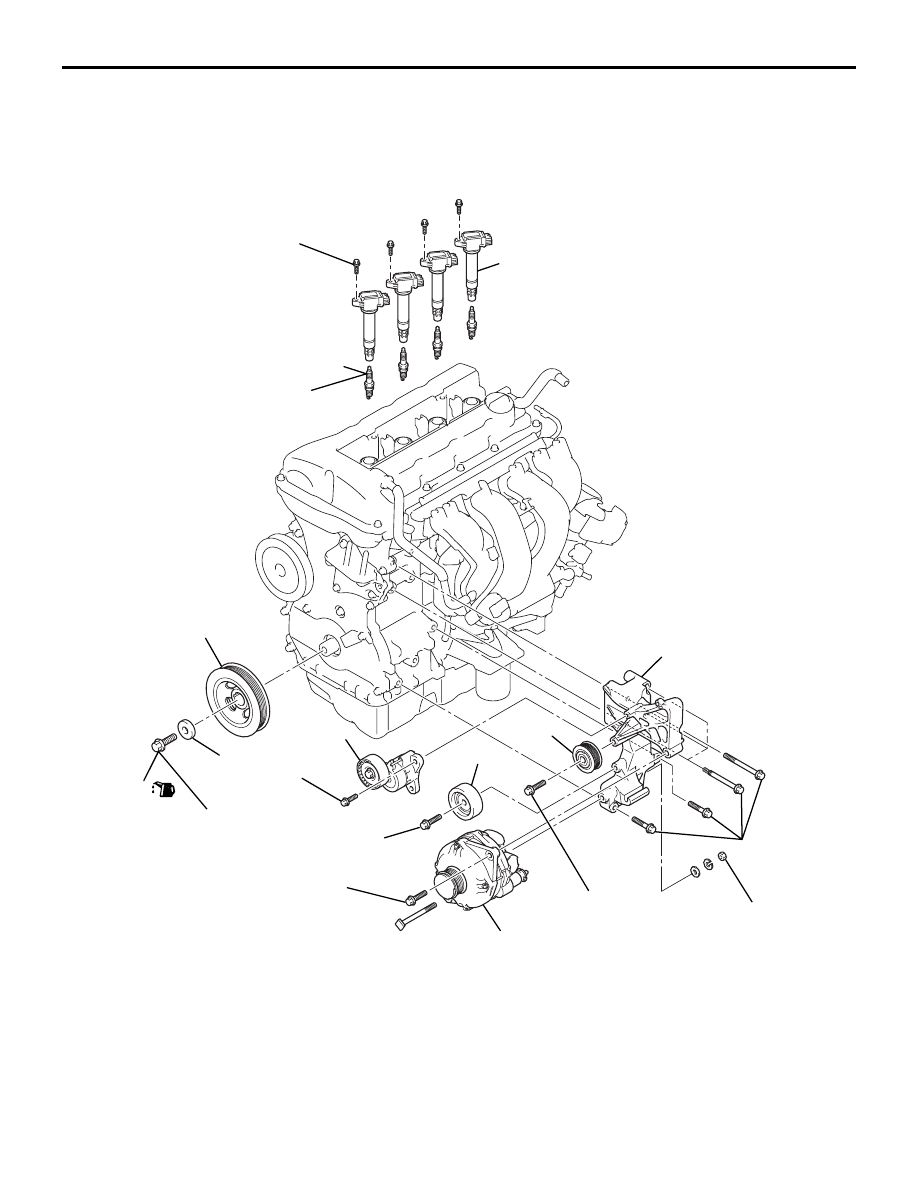
ALTERNATOR AND IGNITION SYSTEM

ENGINE OVERHAUL

11B-10

ALTERNATOR AND IGNITION SYSTEM

REMOVAL AND INSTALLATION

M1113001002718

AKB00725AB

1

2

44 ± 10 N·m

210 N·m

22 ± 4 N·m

44 ± 10 N·m

25 ± 5 N·m

10 ± 2 N·m

3

6

7

8

9

10

44 ± 8 N·m

44 ± 8 N·m

44 ± 8 N·m

5

4

Removal sequence 

1. Idler pulley
2. Idler pulley

>>

C

<<

3. Alternator

>>

C

<<

4. Accessory bracket
5. Auto tensioner

<<

A

>>

>>

B

<<

6. Crankshaft pulley centre bolt

>>

B

<<

7. Crankshaft pulley washer

>>

B

<<

8. Crankshaft pulley
9. Ignition coil

<<

B

>>

>>

A

<<

10. Spark plug

Removal sequence (Continued)

ALTERNATOR AND IGNITION SYSTEM

ENGINE OVERHAUL

11B-11

REMOVAL SERVICE POINTS

<<A>> CRANKSHAFT PULLEY CENTRE 
BOLT REMOVAL

AK502869AC

MB991883

1. Use special tool Flywheel stopper (MB991883) to 

secure the drive plate.

2. Remove the crankshaft pulley centre bolt.

<<B>> SPARK PLUG REMOVAL

AK600875

MB991398

AB

Spark plug

Using special tool Spark plug wrench (MB991398), 
remove the spark plug.

INSTALLATION SERVICE POINTS

>>A<< SPARK PLUG INSTALLATION

AK600875

MB991398

AB

Spark plug

Use special tool Spark plug wrench (MB991398), 
tighten the spark plug to specified torque of 25 

± 5 

N

⋅m.

>>B<< CRANKSHAFT PULLEY / 
CRANKSHAFT PULLEY WASHER / 
CRANKSHAFT PULLEY CENTRE BOLT 
INSTALLATION

AK503335

AC

MB991883

1. Use special tool Flywheel stopper (MB991883) to 

secure the drive plate.

AK602911

AJ

Engine front

Washer

Crankshaft

Crankshaft pulley

Crankshaft 
pulley bolt

Crankshaft
sprocket

: Wipe clean with a rag.
: Wipe clean with a rag and degrease.
: Wipe clean with a rag, degrease and
  apply a small amount of engine oil.

2. Wipe off the dirt on the crankshaft pulley washer 

and on the thread hole of the crankshaft using a 
rag.

3. Wipe off the dirt on the crankshaft pulley and the 

crankshaft sprocket using a rag, and then remove 
the grease from the portion shown in the 
illustration.

NOTE: Remove grease to prevent the coefficient 
of friction of the pressing portion from declining 
due to adhesion of oil.

4. Install the crankshaft pulley.

ALTERNATOR AND IGNITION SYSTEM

ENGINE OVERHAUL

11B-12

5. Apply an appropriate and minimum amount of 

engine oil to the threaded portion of the crankshaft 
and lower part of the flange.

6. With the chamfered side on the inside of the 

washer facing the bolt top, install the crankshaft 
pulley washer to the crankshaft pulley centre bolt.

7. Tighten the crankshaft pulley centre bolt to the 

specified torque of 210 N

⋅m.

>>C<< ALTERNATOR INSTALLATION

AKC00006

1

2

AB

1. Temporarily tighten alternator bolt and nut.

2. First tighten the upper mounting bolt to the 

specified torque, and then tighten the lower nut.

Specified torque: 44 

± 10 Nm

THROTTLE BODY

ENGINE OVERHAUL

11B-13

THROTTLE BODY

REMOVAL AND INSTALLATION

M1113009800347

AKC00007AB

4

7

8

4.0 ± 1.0 N·m

1

2

3

11 ± 1 N·m

9

10

5

9.5 ± 2.5 N·m

6

4.0 ± 1.0 N·m

Removal steps 

1. Vacuum pipe and hose
2. Purge hose
3. Chamber
4. Throttle body stay
5. Throttle body
6. Throttle body gasket
7. Solenoid valve
8. O-ring

>>A<<

9. Manifold absolute pressure (MAP) 

sensor

10. O-ring

INSTALLATION SERVICE POINTS

>>A<< MANIFOLD ABSOLUTE PRES-
SURE (MAP) SENSOR INSTALLATION

CAUTION

• Install the manifold absolute pressure (MAP) 

sensor, taking care not to give a shock to it.

• Do not use a manifold absolute pressure 

(MAP) sensor that has fallen down.


Content   ..  262  263  264  265   ..