Mitsubishi Outlander (2013+). Manual - part 139
 

  Index      Mitsubishi     Mitsubishi Outlander - service repair manual 2013 year


Search            


Content   ..  137  138  139  140   ..


Mitsubishi Outlander (2013+). Manual - part 139


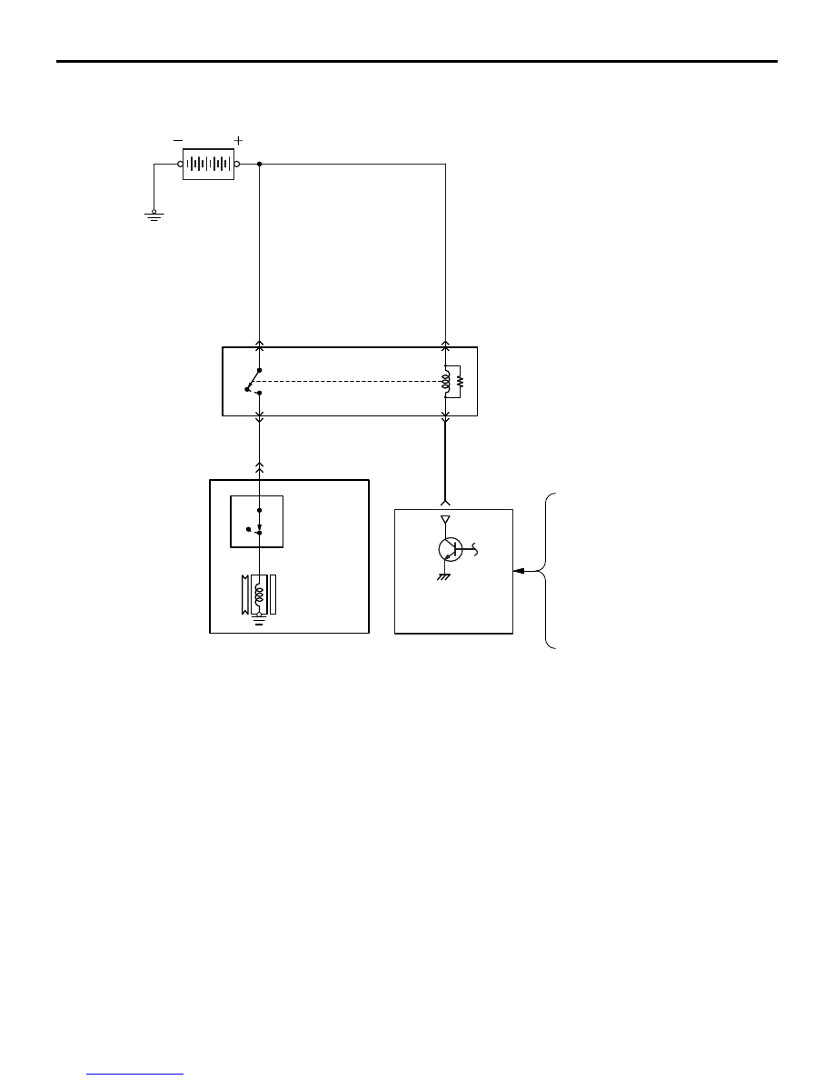
A/C COMPRESSOR RELAY CONTROL

MULTIPOINT FUEL INJECTION (MPI)

13A-40

A/C COMPRESSOR RELAY CONTROL

M2132034500722

After the A/C switch is turned ON and A/C compres-
sor relay reaches a state where it can turn ON, 
engine-ECU turns ON the A/C compressor relay and 
drives the A/C compressor. In order to prevent 
change in engine speed due to increased load of 
driving the compressor, it controls the A/C compres-

sor relay to drive the A/C compressor after idle-up is 
complete. Also, in order to secure acceleration per-
formance, it turns OFF the A/C compressor relay for 
a fixed amount of time, if the throttle opening angle 
increases beyond a prescribed limit.

AK800141

OFF

ON

AH

Battery

A/C compressor relay

A/C compressor
assembly

A/C compressor
relay control

A/C compressor
clutch

A/C
refrigerant
temperature
switch

OFF

ON

Engine-ECU

A/C switch (CAN)

Crank angle sensor

Accelerator pedal position sensor

Vehicle speed signal (CAN)

Inhibitor switch (CAN)

Downloaded from 

www.Manualslib.com


manuals search engine


ALTERNATOR CONTROL

MULTIPOINT FUEL INJECTION (MPI)

13A-41

ALTERNATOR CONTROL

M2132025000785

During engine idle operation, engine-ECU controls 
duty of conduction between alternator G terminal and 
earth. (G terminal duty is controlled to be the same 
as ON duty of the power transistor inside the voltage 
regulator). If headlamps etc. are turned on while 
engine is idling, the consumed current increases 
suddenly, but by gradually increasing the alternator 
G terminal OFF duty, engine-ECU restricts sudden 

increase in alternator output current and output cur-
rent is increased only gradually. (Battery current is 
supplied to the headlamp etc. till alternator produces 
sufficient current.) Thus, engine-ECU prevents 
change in idle speed due to sudden increase of 
engine load.

PURGE CONTROL

M2132027500106

Refer to GROUP 17 

− Emission Control − Evapora-

tive Emission Control System 

P.17-16

.

CONTROLLER AREA NETWORK (CAN)

M2132019000957

CAN communication is established to ensure the reli-
able transmission of information. Refer to GROUP 
54C 

− General Information 

P.54C-2

.

DIAGNOSIS SYSTEM

M2132009002093

Engine-ECU has been provided with the following 
functions for easier system inspection. Refer to the 
workshop manual for the details about each item.

• Freeze-frame data function

• Diagnosis code function

• Data list function

• Actuator test function

AK602242AL

Alternator G terminal

Alternator FR terminal

Alternator

Engine coolant 
temperature sensor

Crank angle sensor

A/C switch (CAN)

Ignition switch-ST

E

ngine-ECU

Downloaded from 

www.Manualslib.com


manuals search engine


NOTES

Downloaded from 

www.Manualslib.com


manuals search engine


13B-1

GROUP 13B

FUEL SUPPLY

CONTENTS

GENERAL INFORMATION . . . . . . . .

13B-2

FUEL TANK  . . . . . . . . . . . . . . . . . . . .

13B-3

Downloaded from 

www.Manualslib.com


manuals search engine


Content   ..  137  138  139  140   ..