Mitsubishi Outlander (2013+). Manual - part 118
 

  Index      Mitsubishi     Mitsubishi Outlander - service repair manual 2013 year


Search            


Content   ..  116  117  118  119   ..


Mitsubishi Outlander (2013+). Manual - part 118


HEATER CONTROL

HEATER, AIR CONDITIONER AND VENTILATION

55-10

HEATER CONTROL

M2551000900904

WITHOUT DUAL A/C

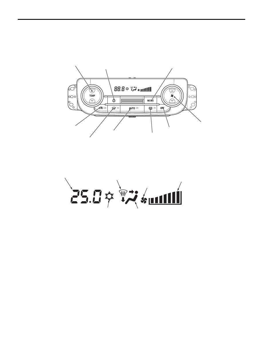
LCD panel 


<WITHOUT DUAL A/C>

ACB05984

A/C switch

Temperature set switch

Air outlet 
changeover switch

Defogger switch

Outside/inside air 
changeover switch

Fan mode 
changeover switch

AUTO switch

Rear defogger switch

OFF switch

AB

ACB05986

Air volume 
display

Illuminates at 
A/C ON mode

AB

Air outlet display

Illuminates while 
the blower motor is on

Inside/outside 
air display

Set temperature 
display

AIR CONDITIONER CONTROL SYSTEM

HEATER, AIR CONDITIONER AND VENTILATION

55-11

DUAL A/C

LCD panel <DUAL A/C>

The following heater controller has been adopted.

• To enhance luxurious appearance and conven-

ience, a liquid crystal display panel has been 
adopted.

• A white character LCD is adopted in order to pro-

vide a better visibility.

• Ergonomic layout of the control panel allows the 

driver to check the current status without less eye 
movement.

• The smoke-shaded LCD screen provides a luxury 

image.

AIR CONDITIONER CONTROL SYSTEM

M2551002800033

General

The air conditioner system with following features 
has been adopted.

• If the heater fan runs at higher stage, the recircu-

lation ratio of heated air will be increased, thus 
improving heating performance.

• The heating performance is enhanced by 

increasing air volume.

• The heating performance is enhanced by restrict-

ing minimum air volume at low ambient tempera-
ture (-5

°C or less).

• The interior temperature sensor can measure 

temperature more precisely due to better sealing 
around it. This improves the response and com-
fort of the automatic air conditioner.

ACB05404

A/C switch

Temperature set switch (LH)

Air outlet 
changeover switch

Defogger switch

Outside/inside air 
changeover switch

AUTO switch

Rear defogger switch

OFF switch

AC

Fan mode 
changeover switch

Temperature set switch (RH)

ACB05985

Air volume 
display

Illuminates at 
A/C ON mode

Illuminates 
at DUAL mode

AB

Air outlet display

Set temperature display 
(front passenger's side)

Illuminates while 
the blower motor is on

Inside/outside 
air display

Set temperature 
display (driver's side)

CUSTOMIZATION FUNCTION

HEATER, AIR CONDITIONER AND VENTILATION

55-12

CONTROL

FORCED DEF CONTROL

When air outlet position is switched to DEF, A/C is 
automatically turned ON, and outside/inside air 
selection damper is set to the fresh air position to 
quickly defrost the windshield screen.

MAX COOL, MAX HOT CONTROL 

When the set temperature is at MAX COOL (15

°C) or 

at MAX HOT (29

°C) with the air outlet and air volume 

at the AUTO positions, the following controls are 
made automatically by the A/C-ECU.

NOTE: "*" indicates that when the automatic control 
is not cancelled using the customise function, the 
manual operation is disabled.

IDLE-UP CONTROL 

A/C-ECU and the engine-ECU communicate with 
each other through the CAN communication. The 
idle-up speed of the engine is controlled in two steps 
depending on the A/C load to secure the air cooling 
performance during summer and to enhance fuel 
economy in seasons with moderate temperature.

DETECTION CONTROL FOR 
REFRIGERANT LEAKS 

A/C-ECU determines if the refrigerant amount is less 
than specified or refrigerant pressure is abnormal by 
using the ambient temperature (ambient temperature 
sensor to measure refrigerant inflation rate) and 
refrigerant pressure (measured by the A/C pressure 
sensor). When refrigerant amount or refrigerant pres-
sure is judged abnormal, the compressor is cut-off to 
protect the A/C system.

PROTECTION CONTROL AT AIR BAG 
DEPLOYMENT (DURING COLLISION)

When the air bag deployment is detected, the A/C 
system is stopped.

COMMUNICATION

A/C-ECU performs the signal transmission and 
reception with each ECU via CAN (Controller Area 
Network)*. 

NOTE: *: For details of CAN communication, refer to 
GROUP 54C 

 Controller Area Network .

DIAGNOSTIC FUNCTION

A/C-ECU has the following functions for easier sys-
tem checks.

• DIAGNOSTIC FUNCTION

• Service data output

• Actuator test

NOTE: For each item, refer to the Workshop Manual.

CUSTOMIZATION FUNCTION

M2551003000018

By operating the M.U.T.-III ETACS system, the fol-
lowing functions can be customised. The pro-
grammed information is held even when the battery 
is disconnected.

Subject to 
control

MAX COOL

MAX HOT

Air mix 
damper

MAX COOL 
position

MAX HOT 
position

Air outlet 
mode

FACE position

FOOT position

Air volume

Maximum

Maximum

Outside/insid
e air 
selection 
damper

Air recirculation 
position*

Fresh air 
position*

Air 
conditioner 
switch

ON*

OFF*

CUSTOMIZATION FUNCTION

HEATER, AIR CONDITIONER AND VENTILATION

55-13

Adjustment 
item (M.U.T.-III 
display)

Adjustment item

Adjusting content 
(M.U.T.-III display)

Adjusting content

A/C 
Recirculation 
Control

With/without 
inside/outside air 
automatic control 
function

Disable

No function

Enable

With function (Initial condition)

A/C Switch 
Control

With/without A/C 
automatic control 
function

Disable

No function

Enable

With function (Initial condition)

A/C Sensible 
temp. 
customize

Adjusting mean 
value for 
temperature setting

-2

Decreases the control temperature two 
degrees than the temperature displayed 
on the LCD.

-1

Decreases the control temperature one 
degree than the temperature displayed on 
the LCD.

0

No change (Initial condition)

1

Increases the control temperature one 
degree than the temperature displayed on 
the LCD.

2

Increases the control temperature two 
degrees than the temperature displayed 
on the LCD.

FOOT / DEF Air 
outlet ratio

Changes air 
distribution rate for 
DEF/FOOT vents 
during manual 
operation.

Normal

D/F2 (Initial condition)

FOOT > DEF

D/F1(more to FOOT vent): More air flows 
through FOOT vents.

FOOT < DEF

D/F3(more to DEF vent): More air flows 
through DEF vents.

FACE / FOOT 
Air outlet ratio

Changes air 
distribution rate for 
FACE/FOOT vents 
during manual 
operation.

Normal

B/L2 (Initial condition)

FACE > FOOT

B/L1(more to FACE vent): More air flows 
through FACE vents.

FACE < FOOT

B/L3(more to FOOT vent): More air flows 
through FOOT vents.

Auto Rear 
Defogger(Engin
e Start)

When ambient 
temperature is 3 
degree or less, the 
rear defogger will 
be turned on 
automatically. (The 
rear window 
defogger has never 
been activated 
since the ignition 
switch was turned 
on last time)

Disable

No function (Initial condition)

Enable

With function


Content   ..  116  117  118  119   ..