Mitsubishi Outlander (2013+). Manual - part 30
 

  Index      Mitsubishi     Mitsubishi Outlander - service repair manual 2013 year


Search            


Content   ..  28  29  30  31   ..


Mitsubishi Outlander (2013+). Manual - part 30


BASE ENGINE

ENGINE MECHANICAL

11-3

BASE ENGINE

M2112001002194

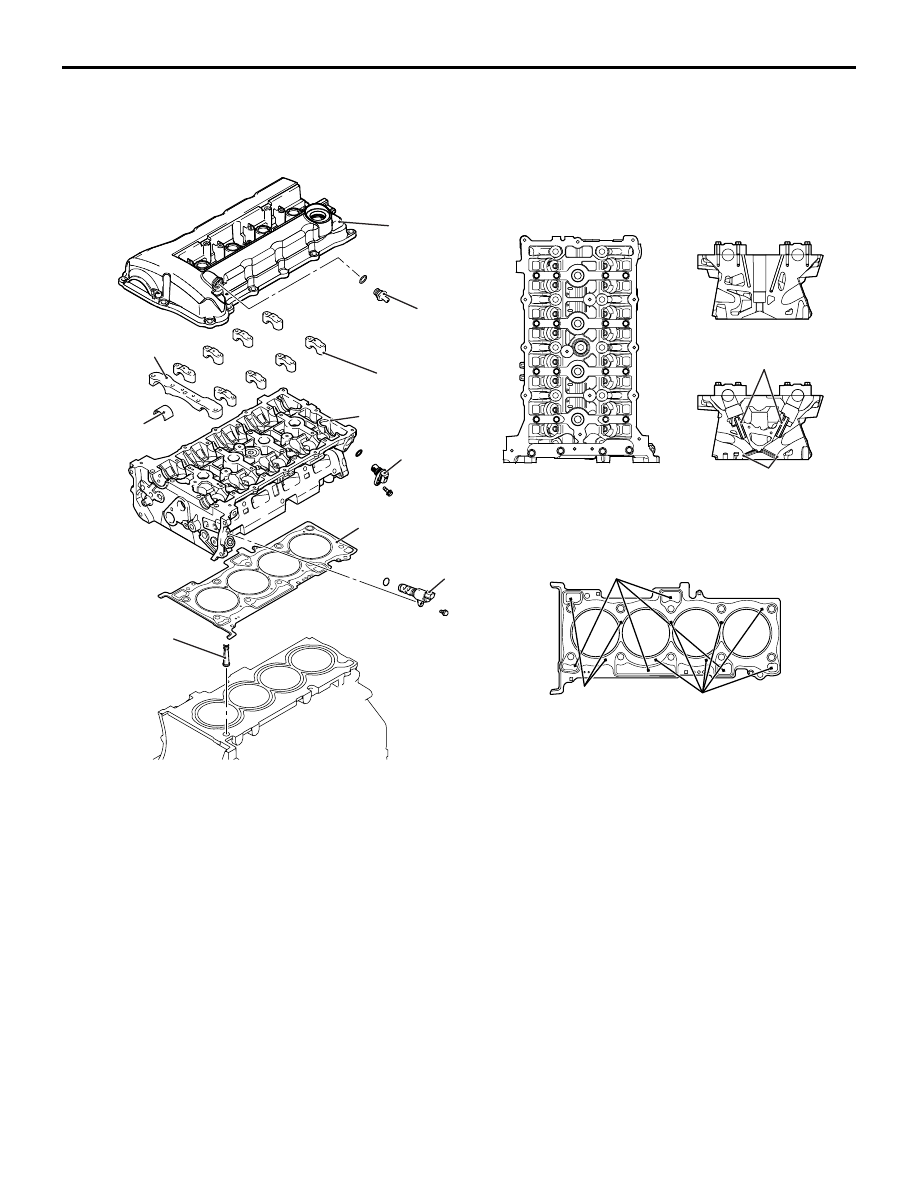
CYLINDER HEAD RELATION

1. CYLINDER HEAD COVER

• A Plastic cylinder head cover has been adopted.

2. PCV VALVE

3. FRONT CAMSHAFT BEARING CAP

• On each camshaft, the thrust load is supported 

by No. 4 bearing. The No. 1 bearings for the 
intake and exhaust camshafts have a common 
bearing cap.

4. CAMSHAFT BEARING CAP

• Each of the intake and exhaust camshafts is sup-

ported by five bearings.

5. CAMSHAFT BEARING

6. OIL FEEDER CONTROL VALVE

7. OIL FEEDER CONTROL VALVE FILTER

8. CYLINDER HEAD

• The cylinder head is made of aluminium alloy, 

which is lightweight and has an excellent cooling 
efficiency. The intake and exhaust ports are 
arranged in a cross-flow construction. Each cylin-
der has a pair of intake ports on one side and a 
pair of exhaust ports on the other side.

9. CYLINDER HEAD GASKET

• A dual-layer, metal type cylinder head gasket that 

excels in heat resistance and sealing perform-
ance has been adopted.

10.VALVE GUIDE

• Valve guides that are common to both the inlet 

and exhaust have been adopted.

11.VALVE SEAT

• Sintered alloy valve seats have been adopted.

12.CAMSHAFT POSITION SENSOR

AKB00849

Oil feeder control
valve filter

Oil hole

Water hole

Cylinder head gasket

Valve guide

Front camshaft
bearing cap

Camshaft bearing cap

PCV valve

Cylinder head cover

Valve seat

Camshaft 
bearing

Cylinder head

Oil feeder control valve

Water hole

AB

Camshaft position 
sensor

BASE ENGINE

ENGINE MECHANICAL

11-4

CYLINDER BLOCK

A cylinder block made of an aluminium alloy has 
been adopted for weight reduction.
Five bearings are provided for the crankshaft jour-
nals and the No. 3 bearing sustains the thrust load of 
the crankshaft.
The water jacket is the full Siamese type.
1. CYLINDER BLOCK

• The cylinder block is made of lightweight alumin-

ium alloy.

The water jacket is of a full-seamless design.

2. CRANKSHAFT BEARING CAP

• The crankshaft journal is supported by four bear-

ings. The crankshaft thrust load is supported by 
No. 3 bearing.

3. LADDERFRAME

AKB00850

Cylinder block

Ladder frame

Crankshaft oil seal

Crankshaft bearing cap

AB

Item

4B11

4B12

Overall height 
mm

230.1

240.1

Bore mm

86

88

Bore pitch mm

96

96

Stroke mm

86

97

BASE ENGINE

ENGINE MECHANICAL

11-5

PISTON RELATION

1. PISTON

• The pistons are made of a special aluminium 

alloy. Their weight has been reduced by lowering 
their overall height and increasing the depression 
at each end of the piston pin. The piston pin hole 
centre is offset 0.8 mm towards the thrust side of 
the piston centre. The skirt portion along the 
perimeter of the piston is finished with streaks 
that excel in oil retention and seizure resistance.

2. PISTON PIN

• The piston pin is of a semi-floating type, press-fit-

ted into the connecting rod small end while capa-
ble of floating relative to the piston.

3. CONNECTING ROD

• The connecting rod is made of highly rigid, forged 

carbon steel. The rod portion has an H-shaped 
cross section. The connecting rod big end bear-
ing is lubricated through an oil passage running 
from the main journal to the crankshaft pin.

4. PISTON RING

• Each piston is provided with No. 1 and No. 2 

compression rings and an oil ring.

5. CONNECTING ROD BEARING

• The upper and lower connecting rod bearing 

halves are identical. The connecting rod bearing 
is equipped with back metal. While the bearing 
itself is made of aluminium alloy, the back metal 
is normally made of steel sheet. The connecting 
rod bearing is narrower than the bearing cap, this 
is to minimize wear.

AKB00851

AB

Piston ring No.1

Spacer

Rail

Maker mark

Piston ring No.2

Oil ring

Piston ring No.1

Piston ring No.2

Oil ring

Connecting rod bearing

Connecting 
rod

Piston

<4B11>

<4B12>

Piston pin

BASE ENGINE

ENGINE MECHANICAL

11-6

CRANKSHAFT RELATION

1. CRANK SHAFT

• A casted crankshaft is used for the crankshaft. 

The crankshaft consists of five main bearings and 
eight balance weights. The crankshaft pins are 
arranged at 180

° intervals. The oil hole supplies 

lubrication oil from the journal to the crank pin. A 
crankshaft sprocket and an oil pump drive gear 
shaft are shrink-fitted onto the front of the crank-
shaft.

2. CRANKSHAFT BEARING

• The upper crankshaft bearing (with oil groove) is 

located on the cylinder block side while the lower 
bearing (without oil groove) is held by the bearing 
cap.The crankshaft bearing is equipped with back 
metal. While the bearing itself is made of alumin-
ium alloy, the back metal is made of steel sheet.

3. THRUST BEARING

• A thrust bearing is installed on both sides of the 

No. 3 crankshaft bearing.

4. CRANKSHAFT PULLEY

• The crankshaft pulley is made of cast-iron and 

rubber. The pulley has grooves to engage with a 
V-ribbed belt (six ribs), which drives an alternator 
and a water pump and an A/C compressor. An 
ignition timing mark (notch) is stamped on the 
flange of the pulley. The crankshaft pulley is 
equipped with a torsional damper to minimize the 
torsional vibration of the crankshaft as well as 
substantially reduce noise and vibration at the 
high speed range.

5. CRANKSHAFT SENSING RING

The crankshaft is also fitted with a crankshaft 
sensing ring.

6. DRIVE PLATE

• A cast iron ring gear is a shrink fit in the steel 

plate of the drive plate. The drive plate is installed 
by tightening six bolts. 

AKB00852

Drive plate

Crankshaft
sprocket

Crankshaft 
sensing ring

Crankshaft

Crankshaft
pulley

Thrust bearing

Upper crankshaft 
bearing

Lower crankshaft 
bearing

Oil
groove

Adapter plate

Crankshaft
sprocket

Crankshaft sensing ring

Crankshaft

Oil hole

Balance weight

Balance weight

Balance weight

AB


Content   ..  28  29  30  31   ..