Mitsubishi Outlander (2003+). Manual - part 437
DIAGNOSTIC TROUBLE CODE PROCEDURES
SMART WIRING SYSTEM (SWS) NOT USING SWS MONITOR
54B-37
Step 6. Check that the hazard warning lamps
illuminate.
When the ignition switch is turned to the LOCK
(OFF) position, check if the hazard warning lamps
illuminate.
Q: Is the check result normal?
YES :
Refer to diagnosis code No.12 "Column
switch fault or improper connection
NO :
Refer to inspection procedure A-2 "Check
the ETACS-ECU battery power supply
circuit
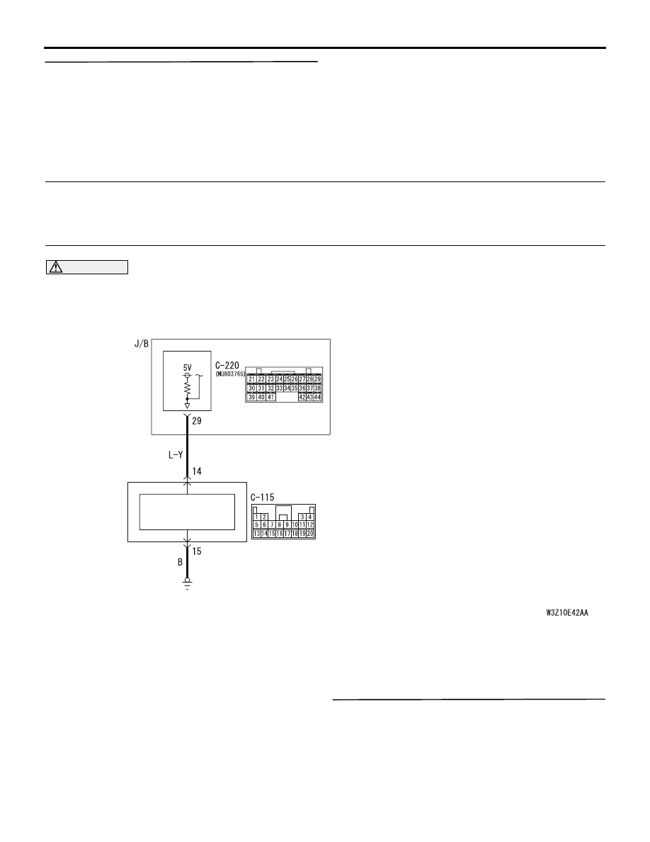
Diagnosis code 31: Open circuit in signal line between the SRS-ECU and the ETACS-ECU (impact
detection signal)
Diagnosis code 32: Short circuit in signal line between the SRS-ECU and the ETACS-ECU (impact
detection signal)
CAUTION
Whenever the ECU is replaced, ensure that the
input signal circuit is normal.
DIAGNOSIS CODE SET CONDITIONS
If the voltage in the signal line between the
SRS-ECU and the ETACS-ECU has exceeded 4.6 V
for 40 milliseconds or more, the ETACS-ECU will set
diagnosis code No.31 as an open circuit. If the signal
line voltage has reached 1.5 V or less for at least 2.5
seconds, the ETACS-ECU will set diagnosis code
No.32 as a short circuit. If the ignition switch is turned
off, the ETACS-ECU will stop sending the diagnosis
code.
POSSIBLE CAUSES
•
Malfunction of the SRS-ECU
•
Malfunction of the ETACS-ECU
•
Damaged harness wires and connectors
DIAGNOSTIC PROCEDURE
Step 1. Use the MUT-II/III to confirm a diagnosis
code.
Check that the SRS-ECU sets a diagnosis code.
Q: Is the check result normal?
YES :
Go to Step 2.
NO :
Refer to GROUP 52B
−
Troubleshooting
Wire colour code
B : Black LG : Light green
G : Green L : Blue
W : White Y : Yellow
SB : Sky blue BR : Brown
O : Orange GR : Gray
R : Red P : Pink V : Violet
IMPACT-DEPENDENT
DOOR UNLOCK
SIGNAL PROCESSING
CIRCUIT
SRS-ECU
ETACS-ECU