Mitsubishi Outlander (2003+). Manual - part 396
 

  Index      Mitsubishi     Mitsubishi Outlander - service repair manual 2003 year


Search            


Content   ..  394  395  396  397   ..


Mitsubishi Outlander (2003+). Manual - part 396


AIR BAG MODULES AND CLOCK SPRING

SUPPLEMENTAL RESTRAINT SYSTEM (SRS)

52B-183

INSTALLATION SERVICE POINTS

>>A<< PRE-INSTALLATION INSPECTION

WARNING

When discarding the air bag module or seat 
back assembly, deploy the air bag as 
specified in the service procedure (Refer to 

P.52B-191

).

1. Even new air bag modules, clock spring and front 

seat back assembly require inspection before 
installation.

2. Connect the negative battery cable.

WARNING

Turn the ignition switch to the "LOCK" (OFF) 
position when connecting and disconnecting 
the MUT-II/III.

3. Connect the MUT-II/III to the diagnosis connector 

(16- pin).

4. Turn the ignition switch to the "ON" position.
5. Read a diagnosis code to refer to that the SRS is 

operating properly except an open in the air bag 
module circuit.

6. Turn the ignition switch to "LOCK" (OFF) position.

WARNING

Wait at least 60 seconds after the 
disconnection of the battery cable before 
any further job (Refer to 

P.52B-3

).

7. Disconnect the negative battery cable and 

insulate with tape.

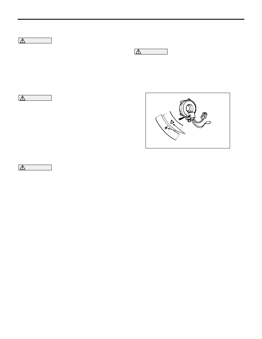
>>B<< CLOCK SPRING INSTALLATION
1. Confirm that the steering wheel is at the 

straight-ahead position.

WARNING

Unless the mating marks are properly 
aligned, the steering wheel gets stuck amid a 
turn or the flat cable in the clock spring is 
cut. These hinder the SRS air bag from 
proper operation, resulting in serious injury 
to the vehicle's driver.

2. Align the mating marks of the clock spring. 

(1) Turn the clock spring clockwise fully. Then turn 

it back approximately 3 3/4 turns 
counterclockwise to align the mating marks.

(2) Then install the clock spring to the column 

switch.

AC300168

Mating marks

AB

AIR BAG MODULES AND CLOCK SPRING

SUPPLEMENTAL RESTRAINT SYSTEM (SRS)

52B-184

>>C<< STEERING WHEEL AND AIR BAG 
MODULE ASSEMBLY INSTALLATION

CAUTION

Be sure when installing the steering wheel, that 
the harness of the clock spring does not become 
caught or tangled.
1. Refer to first that the clock spring has been 

centered properly. Then, install the steering 
wheel.

2. After clamping, turn the steering wheel all the way 

in both directions to confirm that steering is 
normal.

>>D<< POST-INSTALLATION INSPECTION
1. Connect the negative battery cable.
2. Turn the ignition key to "ON" position.

3. Does the SRS warning lamp illuminate for about 7 

seconds, and then remain extinguished for at 
least 5 seconds after turning OFF?

4. If no, refer to troubleshooting (Refer to 

P.52B-11

).

INSPECTION

M1524002500466

AIR BAG MODULE CHECK

WARNING

If any component damage is found during 
the following inspection, replace the air 
bag module(s) with a new one. Dispose of 
the old one according to the specified 
procedure (Refer to 

P.52B-191

).

Never attempt to measure the circuit 
resistance of he air bag module (squib) 
even if you are using the specified tester. 
If the circuit resistance is measured with a 
tester, accidental air bag module(s) 
deployment will result in serious personal 
injury.

1. Check the pad cover for dents, cracks or 

deformation.

2. Check the connectors for damage, the terminals 

for deformation, and the harness for binds.

3. Check the air bag inflator case for dents, cracks or 

deformation.

4. Install the air bag module (driver’s side) to the 

steering wheel and check fit and alignment with 
the wheel. 

5. Install the air bag module (front passenger’s side) 

to the instrument panel and front deck 
crossmember and check fit and alignment.

AC301667

SRS warning lamp

AB

AC300170AB

<Driver's side>

<Front passenger's side>

Inflator case

Connector

Connector

Inflator case

AIR BAG MODULES AND CLOCK SPRING

SUPPLEMENTAL RESTRAINT SYSTEM (SRS)

52B-185

FRONT SEATBACK ASSEMBLY WITH SIDE AIR 
BAG MODULE CHECK

WARNING

If any improper part is found during the 
following inspection, replace the front 
seatback assembly with a new one. 
Dispose of the old one according to the 
specified procedure (Refer to 

P.52B-191

).

Never attempt to measure the circuit 
resistance of the air bag module (squib) 
even if you are using the specified tester. 
If the circuit resistance is measured with a 
tester, accidental air bag deployment will 
result in serious personal injury.

1. Check the air bag module deployment section for 

dents or deformation.

2. Check the connector for damage, the terminals for 

deformation, and the harness for binds.

CLOCK SPRING CHECK

If any malfunction is found in the following 
inspections, replace the clock spring with a new one.
1. Check the connectors and protective tube for 

damage, and the terminals for deformation.

2. Visually check the case for damage.
3. Check to see that there is a charge (continuity) 

between the C-308 clock spring connector 
terminal 1 and C-305 horn switch.

CAUTION

 Do not directly insert a probe, etc. into the 
terminal from the front of the connector.
4.  Insert the special tool harness set (MB991222) 

from behind the C-306 air bag module connector 
(driver's side).

5.  As shown in the Figure, connect the circuit tester 

to the special tool harness set (MB991222) and 
check to see that there is a charge between the 
terminals.

AC300172 AB

Air bag module
deployment
section

1 2 3 4 5 6

AC303008AD

Case

C-308 Clock spring
connector

Protective tube

C-306 Air bag
module connector

C-305 Horn switch

AC303007AD

Clock spring

C-306 Air bag
module connector
(driver's side)

C-306 Air bag
module connector
(driver's side)

Plobe
(MB991222)

Digital
multi-meter

SIDE IMPACT SENSOR

SUPPLEMENTAL RESTRAINT SYSTEM (SRS)

52B-186

SIDE IMPACT SENSOR

REMOVAL AND INSTALLATION

M1524004600243

WARNING

Disconnect the negative battery terminal and wait for 60 seconds or more before starting 
work. Furthermore, the disconnected battery terminal should be covered with tape to 
insulate it.

Never attempt to disassemble or repair the side impact sensors. If faulty, replace it.

Do not drop or subject the side impact sensors to impact or vibration. If denting, cracking, 
deformation, or rust are discovered in the side impact sensors, replace it with a new front 
impact sensor. Discard the old one.

After deployment of an air bag, replace the side impact sensors with a new one.

Never use an ohmmeter on or near the side impact sensors, and use only the special test 
equipment described on 

P.52B-9

.

NOTE: The figure shows the side impact sensor 
(RH).

Pre-removal Operation

Turn the ignition key to the "LOCK" (OFF) position.

Disconnect the Negative Battery Terminal.

AC300142

1

5.0 ± 1.0 N·m

Center pillar

Front of vehicle

AB

Removal steps

Centre pillar trim lower (Refer to 
GROUP 52A 

 Trims 

P.52A-18

).

Seat belt pre-tensioner (Refer to 
GROUP 52A 

 Front seat belt 

P.52A-39

).

1.

Side impact sensor
Installation steps

>>A<<

Pre-installation inspection

>>B<<

1.

Side impact sensor

Seat belt pre-tensioner (Refer to 
GROUP 52A 

 Front seat belt 

P.52A-39

).

Centre pillar trim lower (Refer to 
GROUP 52A 

 Trims 

P.52A-18

).

Negative battery cable connector

>>C<<

Post-installation inspection

Installation steps (Continued)


Content   ..  394  395  396  397   ..